[0009] An object of the present invention is to provide a rotation angle detecting device capable of improving detection accuracy of a rotation angle of an object to be measured by improving
linearity of an output
signal from a magnetic detection element with respect to rotation angles of the object to be measured and a magnet over a full range of a detected angle of the object to be measured. Moreover, an object of the present invention is to provide a rotation angle detecting device capable of preventing the detection accuracy of the rotation angle of the magnet rotating with the rotation of the object to be measured from being lowered by constituting a housing for rotatably holding the magnet therein and a housing for retaining magnetic members and the magnetic detection element therein by a
single component.
[0011] As a result, since an output signal from the magnetic detection element is also suddenly lowered, the output signal approaches an ideal output signal as compared with that in the conventional techniques. Therefore,
linearity of the output signal from the magnetic detection element (linearity of an output variation characteristic of the magnetic detection element) with respect to rotation angles of the object to be measured and the magnet over a full range of the detected angle of the object to be measured can be improved. In particular, since the linearity of the output signal from the magnetic detection element (the linearity of the output variation characteristic of the magnetic detection element) with respect to the rotation angle of the magnet in an area where the air gap is relatively small can be improved, the detection accuracy of the rotation angle of the object to be measured can be improved.
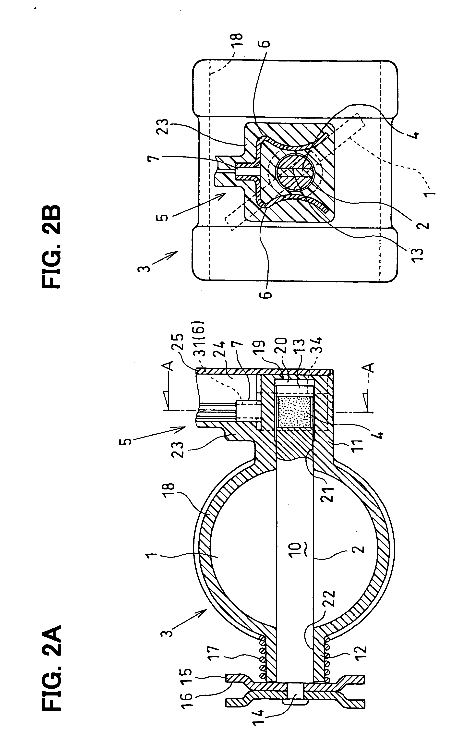
[0013] According to still another aspect of the present invention, by providing a sensor retaining section for retaining a rotation angle sensor including magnetic members and a magnetic detection element, and a magnet holding hole for rotatably holding a magnet therein for a housing integrally formed of a non-magnetic material, a housing for rotatably holding the magnet therein and a housing for retaining the magnetic members and the magnet detection element therein can be constituted by a
single component. As a result, the positional accuracy (combination accuracy) of the magnetic members and the magnetic detection element with respect to the
magnetization direction of the magnet can be easily obtained, thereby reducing a variation in
assembly of the magnet and the magnetic members and the magnetic detection element. Moreover, since a variation is hardly generated in output from the magnetic detection element, the detection accuracy of the rotation angle of the magnet rotating with the rotation of the object to be measured can be prevented from being lowered. Moreover, since a single magnet is provided as a
magnetic field source, the number of components and the number of
assembly steps can be reduced as compared with those in the conventional techniques requiring two magnets. As a result, the overall cost of the rotation angle detecting device can be reduced.
[0014] According to still another aspect of the present invention, the magnetic detection gap between the magnetic members is provided in the middle of the
magnetic circuit including the magnet and the magnetic members so that a positional relation is such that a density of
magnetic flux crossing both magnetically sensitive faces of the magnetic detection element in the plate-thickness direction becomes relatively small with respect to a
magnetization direction of the magnet when the rotation angle of the object to be measured is positioned in the vicinity of the middle angle within the range of use. As a result, if the object to be measured is positioned in the vicinity of the middle angle within the range of use, the density of the
magnetic flux passing through the magnetic detection gap between the magnetic members, that is, the density of the magnetic flux crossing both magnetically sensitive faces of the magnetic detection element in the plate-thickness direction becomes relatively small. Therefore, an output signal from the magnetic detection element has a relatively small value, thereby detecting the rotation angle of the object to be measured in the vicinity of the middle angle. Then, if the magnet rotates in both directions from the vicinity of the middle angle, the output from the magnetic detection element elevates or drops so as to accurately detect the rotation angle of the object to be measured over a wide range.
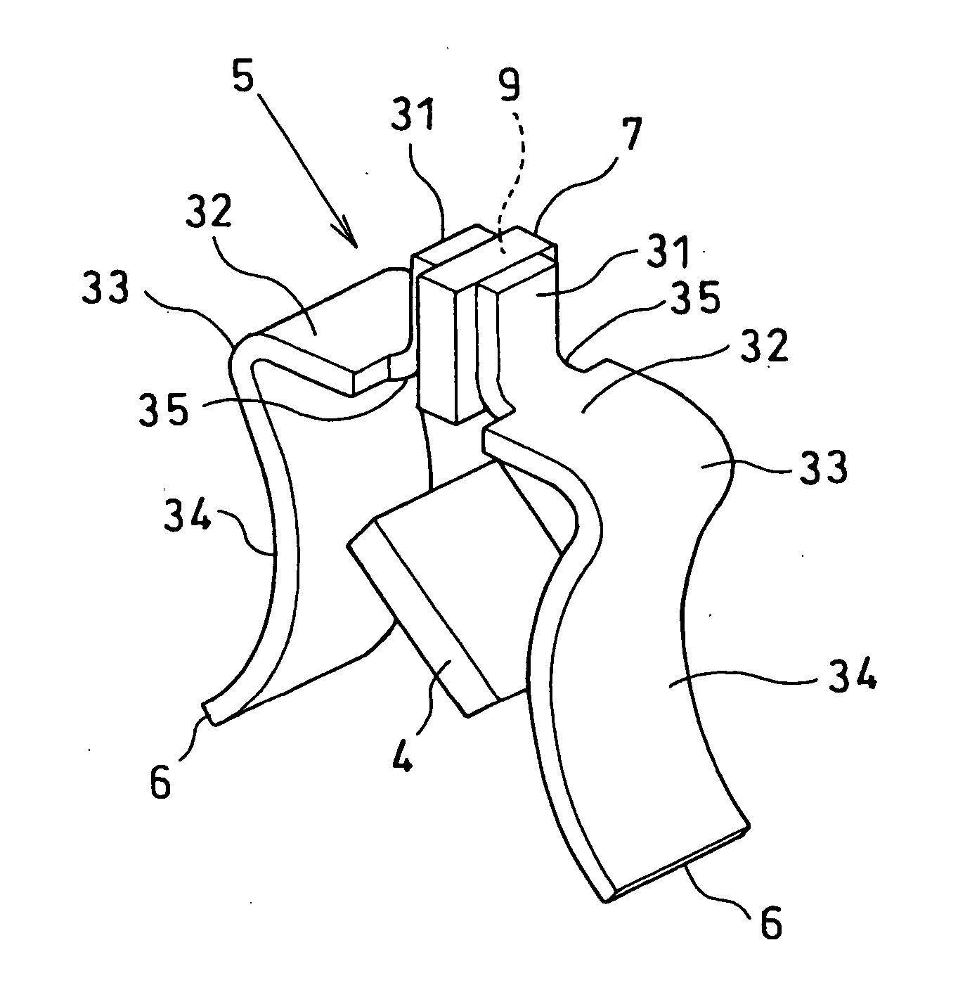
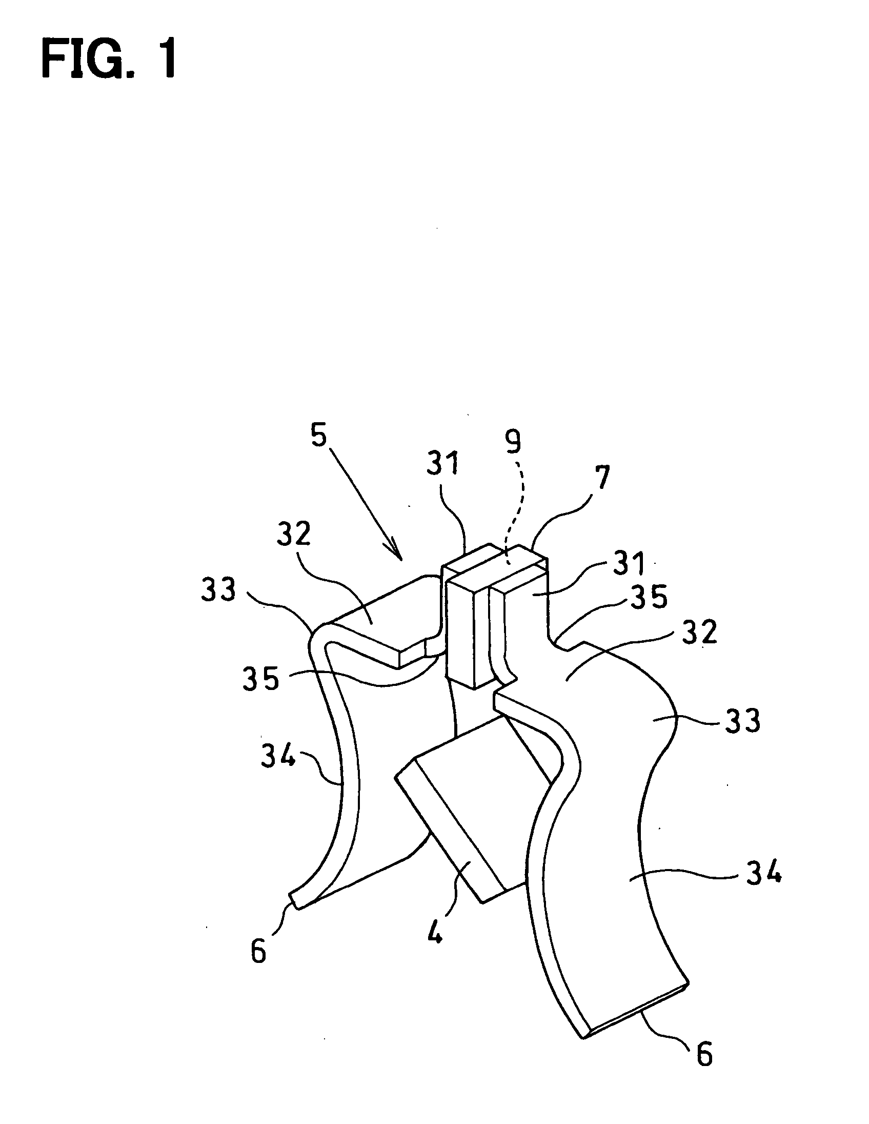
[0015] According to yet another aspect of the present invention, magnetic detection element retaining pieces, each having a smaller width than that of the reverse warp parts for concentrating the magnetic flux of the magnet thereon, are provided for the magnetic members, respectively. Then, if the respective magnetic detection element retaining pieces of the magnetic members are provided so as to be opposed to each other through the magnetic detection gap while being in contact with both magnetically sensitive faces of the magnetic detection element in the plate-thickness direction, the magnetic flux can be concentrated on both magnetically sensitive faces of the magnetic detection element in the plate-thickness direction. As a result, the magnetic flux can be concentrated on both magnetically sensitive faces of the magnetic detection element in the plate-thickness direction efficiently over the range of the rotation angle in which the magnet rotates from the minimum angle to the maximum angle with the rotation of the object to be measured, that is, over a full range of the detected angle of the object to be measured. Therefore, a stable output signal can be obtained from the magnetic detection element.
[0016] According to yet another aspect of the present invention, shoulder parts extended in an approximately straight manner in a direction approximately perpendicularly crossing a center axis direction so as to be separated away from each other are provided for the magnetic members, respectively. Then, through bent parts bent at an approximately
acute angle at ends of the shoulder parts, the ends of the shoulder parts and the ends of the reverse warp parts are connected to each other. The respective magnetic detection element retaining pieces of the magnetic members are provided so as to be bent at an approximately right angle at the ends of the shoulder parts on the magnetic detection gap side so as to be separated away from the magnet. As a result, the magnetic flux can be concentrated on both magnetically sensitive faces of the magnetic detection element in the plate-thickness direction efficiently over the range of a rotation angle in which the magnet rotates from the minimum angle to the maximum angle with the rotation of the object to be measured, that is, a full range of the detected angle of the object to be measured. Therefore, a stable output signal can be obtained from the magnetic detection element.

