User authentication system and room entry/exit management system

a user authentication and management system technology, applied in the field of user authentication systems, can solve problems such as burdening users, and achieve the effect of accurate user authentication

Inactive Publication Date: 2006-06-08
MITSUBISHI ELECTRIC CORP
View PDF8 Cites 32 Cited by
  • Summary
  • Abstract
  • Description
  • Claims
  • Application Information

AI Technical Summary

Benefits of technology

[0012] According to the invention, there is a benefit in that user authentication can be performed accurately without forcing the user special operations such as holding up an IC card to a reader, or pressing a switch in order to express the intention of use.

Problems solved by technology

Therefore, there has been a problem in that, even if an RFID device, in which the communicating range is long, is used, a user is forced to do some operation for authentication, which imposes a burden on the user.

Method used


Image

  • User authentication system and room entry/exit management system
  • User authentication system and room entry/exit management system
  • User authentication system and room entry/exit management system

Examples


embodiment 1

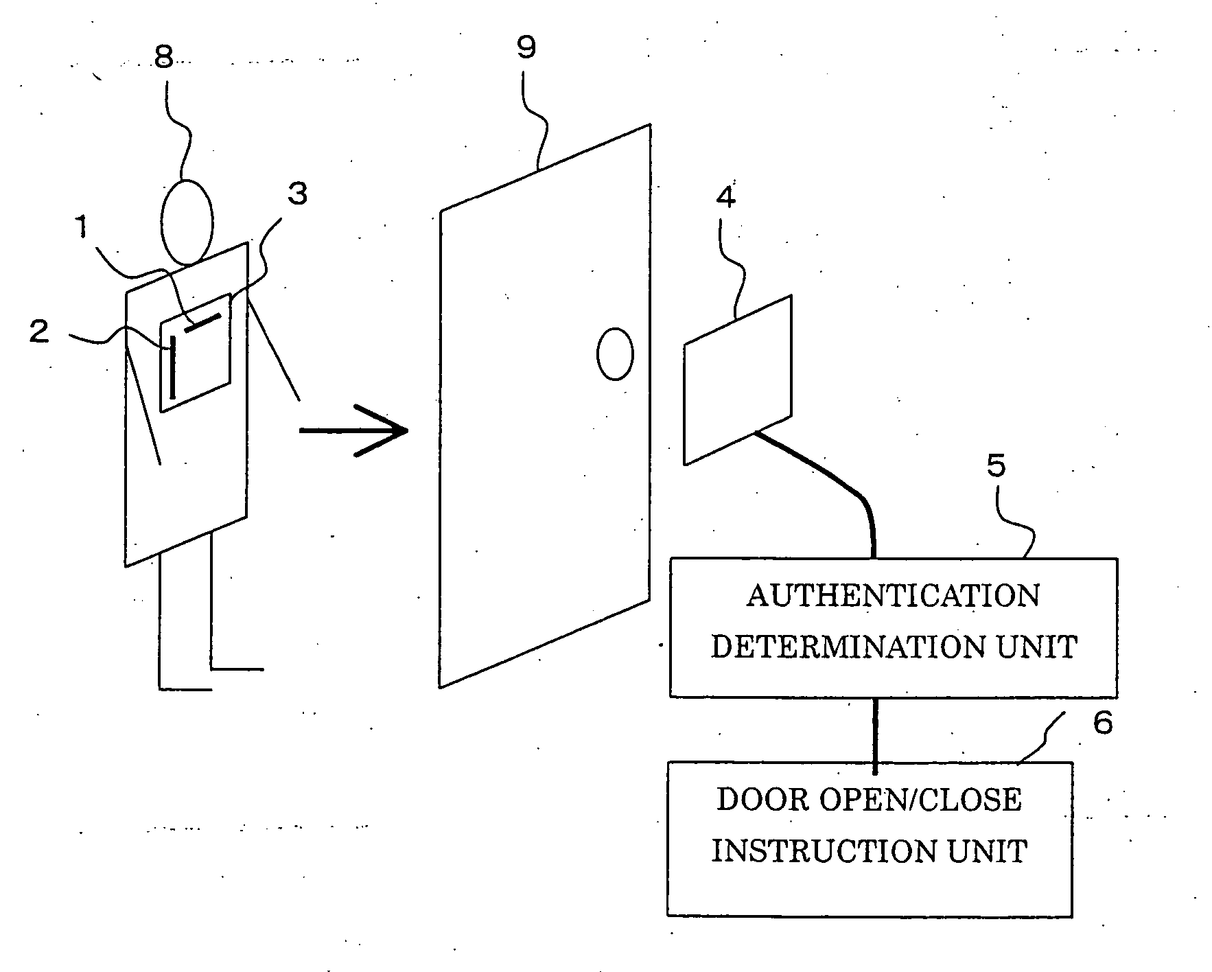
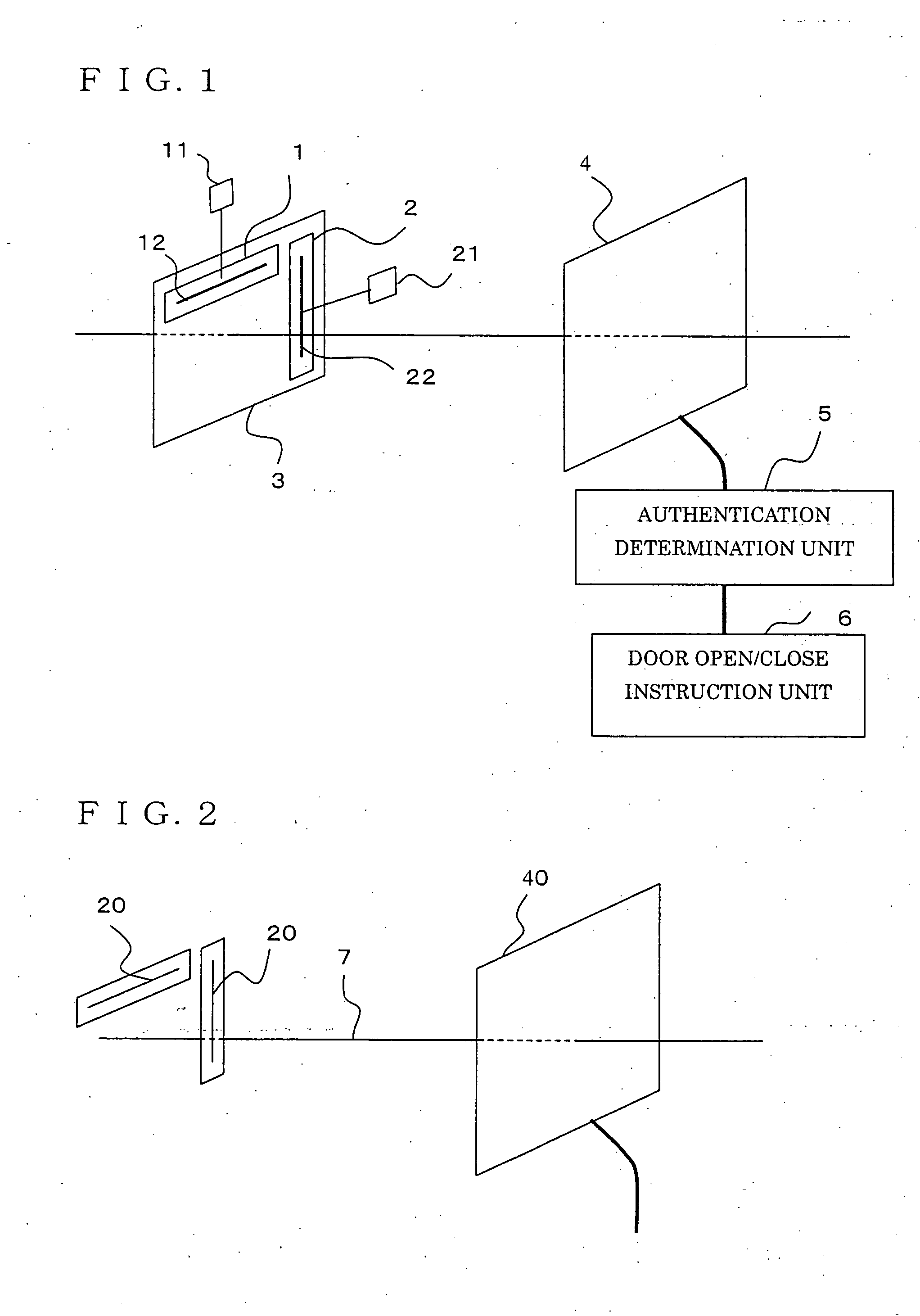
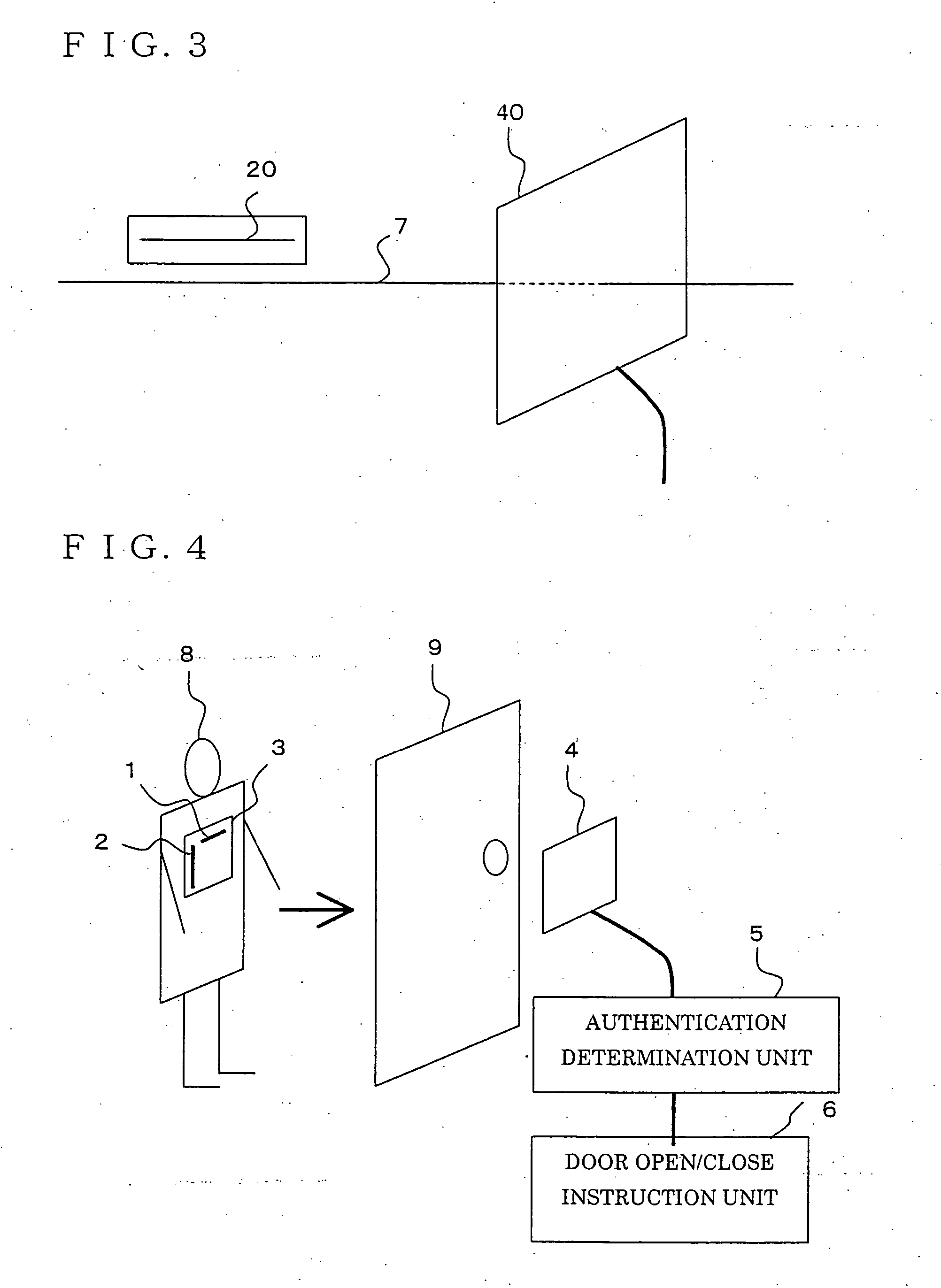
[0019]FIG. 1 is a block diagram illustrating a user authentication system according to Embodiment 1 of the present invention. Hereinafter, a case in which the user authentication system in the embodiment is used for room entry / exit management will be described, and an example in which a door is the object to which use-permission is given will be explained.

[0020] A user holds a tag plate 3, to which an RFID tag A (a first wireless tag) 1, and an RFID tag B (a second wireless tag) 2 are attached. The RFID tag A 1 and the RFID tag B 2 are composed of semiconductor chips (tag chips) 11 and 21, and tag antennas 12 and 22, respectively, and are disposed on the tag plate 3 so that the direction (axial direction) of the tag antenna 12 on the RFID tag A 1 (the first antenna) is perpendicular to the direction (axial direction) of the tag antenna 22 on the RFID tag B 2 (the second antenna). The tag plate 3 aims to keep the positional relationship between the RFID tag A 1 and the RFID tag B 2 ...

embodiment 2

[0032] In Embodiment 1, the authentication determination unit 5 gives use-permission only when the ID code transmitted from the RFID tag A 1 and the ID code transmitted from the RFID tag B 2 are received together during a predetermined period of time. Generally, because an ID code is transmitted not just one time, but constantly, the identical ID code can be received many times during a predetermined period of time. When the RFID tag and the reader antenna are close to each other, and radio waves are strong, the count of receptions of the ID code during a predetermined period of time becomes large.

[0033] In the present Embodiment 2, the tag plate 3 and the reader antenna 4 are configured similarly to those in Embodiment 1 illustrated in FIG. 1, but the configuration of an authentication determination unit 5 is different, and the determination manner is different from that in Embodiment 1. More specifically, the authentication determination unit 5 gives use-permission, only when the...

embodiment 3

[0035] In the present Embodiment 3, the tag plate 3 and the reader antenna 4 are configured similarly to those in Embodiment 1 illustrated in FIG. 1, but the configuration of an authentication determination unit 5 is different, and the determination manner is different from those in Embodiment 1 and Embodiment 2. More specifically, the authentication determination unit 5 is configured so as to count the ID code transmitted from the RFID tag A 1 and the ID code transmitted from the RFID tag B 2 every predetermined period of time, and to determine that the use is permitted, if the ID codes are received together during a predetermined period of time, and if the counts of receptions of the ID codes are not less than a predetermined count, and each ID-code reception count increases at each of predetermined intervals.

[0036] Configured as above, the use-permission is given, only when the user faces the object to use, the user is within a predetermined distance from the object to use, and ...


PUM


Abstract

A user authentication system of the present invention includes: a first wireless tag having first ID data about a user and a first antenna for transmitting the first ID data; a second wireless tag having second ID data different from the first ID data, and a second antenna, perpendicular to the first antenna, for transmitting the second ID data; a wireless-tag receiver for receiving the first ID data transmitted from the first antenna and the second ID data transmitted from the second antenna; and a use-permission determining apparatus for determining whether the ID data received by the receiver matches pre-registered ID data, and for determining, based on timing of or counts of receptions of the first ID data and the second ID data received during a predetermined period of time, whether use is permitted.

Description

BACKGROUND OF THE INVENTION [0001] 1. Field of the Invention [0002] The present invention relates to user authentication systems, and particularly to a user authentication system in which permission to use a facility is given by the communicating of user ID codes via radio waves. In addition, the invention relates to a room entry / exit management system using such a user authentication system. [0003] 2. Description of the Related Art [0004] Conventional user authentication systems include an authentication system that authenticates according to ID codes, using media such as noncontact IC cards that record ID codes (ID data). Typical examples of authentication systems using noncontact IC cards include authentication systems employed for railway automatic ticket gates, room entry / exit management systems, and electronic money. Typical international standards for noncontact IC cards include ISO / IEC14443. The communicable range of noncontact IC cards that meet the standard is about 10 cm....

Claims


Application Information

Patent Timeline
Patent Type & Authority Applications(United States)
IPC IPC(8): G05B19/00B60R25/00E05B49/00G07C9/00
CPCG07C9/00111G07C9/00309G07C2209/63G07C9/28
Inventor HIRAI, TAKAHIDESASAKAWA, KOICHI
Owner MITSUBISHI ELECTRIC CORP
Why Eureka
Try Eureka