Lithographic apparatus and device manufacturing method

a technology of lithographic apparatus and manufacturing method, which is applied in the direction of photomechanical apparatus, instruments, optics, etc., can solve the problems of reducing the accuracy of the images generated by the lithographic apparatus, introducing positional errors into the apparatus, and not constant heat generation within the array of individually controllable elements

Inactive Publication Date: 2006-06-08
ASML NETHERLANDS BV
View PDF24 Cites 31 Cited by
  • Summary
  • Abstract
  • Description
  • Claims
  • Application Information

AI Technical Summary

Benefits of technology

[0015] According to a further aspect of the invention, there is provided a device manufacturing method comprising the following steps. Conditioning a beam of radiation using an illumination system. Using an array of individually controllable elements to impart the beam with a pattern in its cross-section. Projecting the patterned beam of radiation onto a target portion of the substrate. The array of individually controllable elements is thermally coupled to a thermal reservoir having a heat capacity selected such that, in operation, when the array of individually controllable elemen

Problems solved by technology

In lithographic apparatus, components that generate heat can introduce into the apparatus positional errors between components due to thermal expansion.
This, in turn reduces the accuracy of the images g

Method used


Image

  • Lithographic apparatus and device manufacturing method
  • Lithographic apparatus and device manufacturing method
  • Lithographic apparatus and device manufacturing method

Examples


fourth embodiment

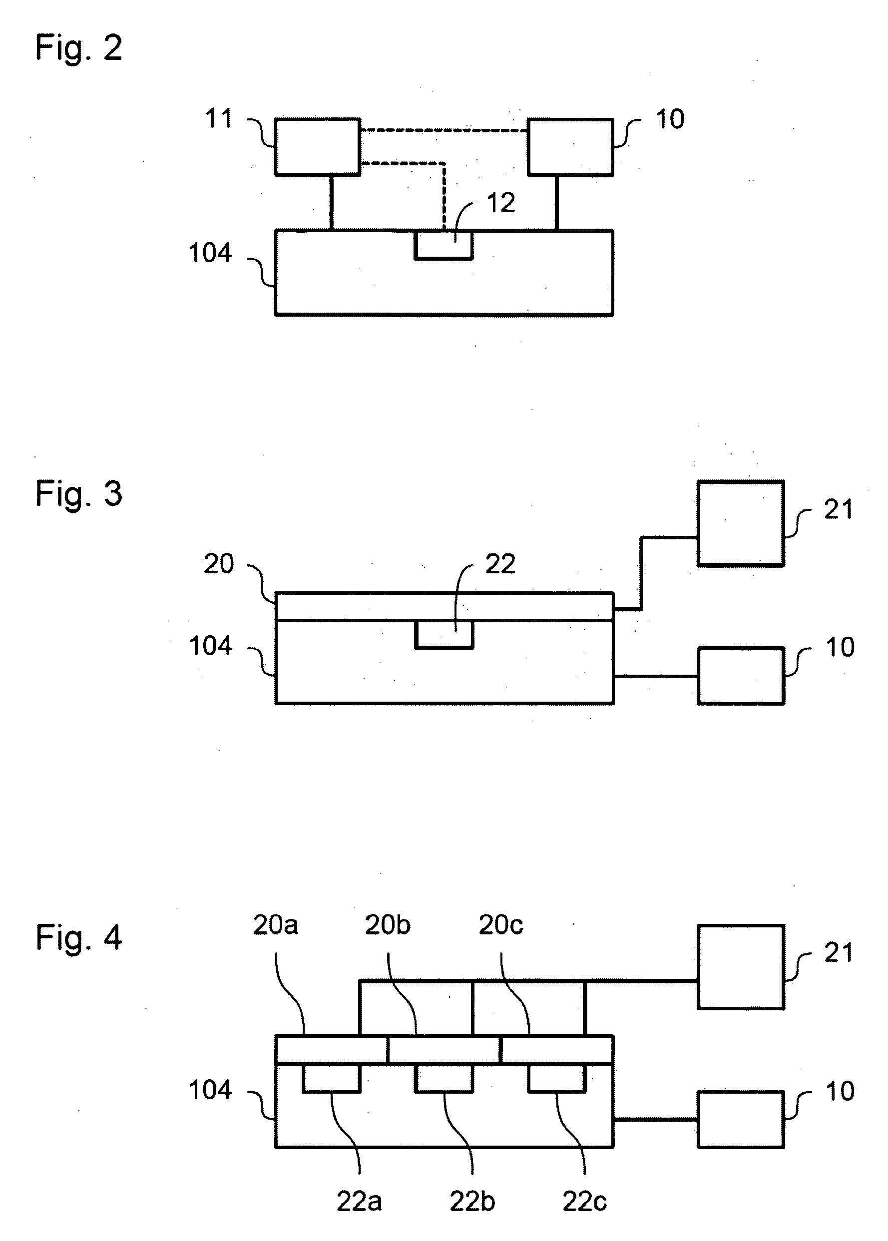
[0068] In one example, the heating element 20 is formed from an insulated resistance wire with a voltage applied across it to generate a current flow. Such an arrangement is simple to control and has a relatively quick response rate, enabling precise control of the temperature with a relatively simple control system. Furthermore, such an arrangement can easily be adapted to provide independent control of the amount of heat generated within different areas of the heating element. However, it will be appreciated that any suitable forms of heating element can be used, such as a conduit containing fluid that is heated in a manner corresponding to the cooling system described below in respect of the

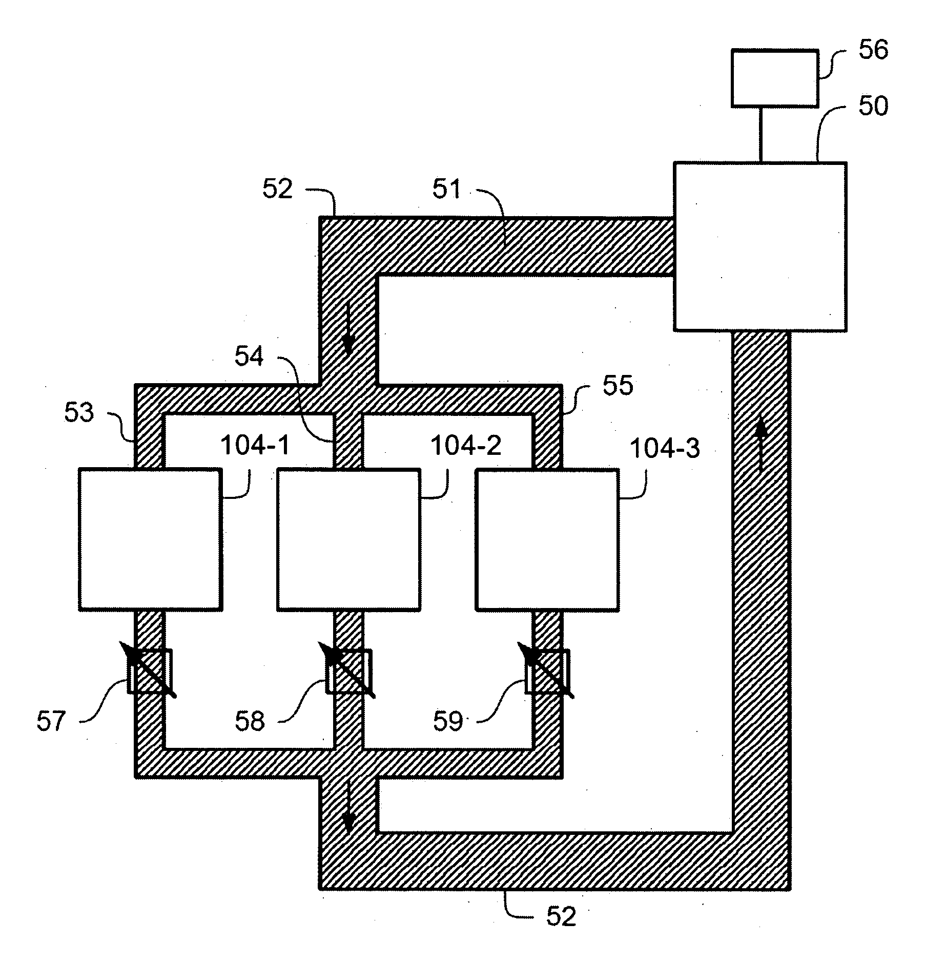
[0069] In one example, the heating element can be in the form of a so-called “heat pipe,” connected between the array of individually controllable elements 104 and a heat source. In such an arrangement, the heat source can, be located away from the main part of the lithographic apparatus. This...

third embodiment

[0093] It will be appreciated that, although the description above has described four different options for managing the heat generated by the use of the array of individually controllable elements as four separate embodiments, they are not exclusive and can be used in conjunction. For example, an array of individually controllable elements can be provided with both a heating element and a cooling element in order to prevent the temperature of the array of individually controllable elements from becoming either too cold or too hot, respectively. Likewise, in an arrangement in which ancillary control signals are provided to the array of individually controllable elements in order to maintain the temperature of the array of individually controllable elements when it would not otherwise be in use (namely when no pattern is to be formed on the array of individually controllable elements in order to pattern a beam of radiation), a heating element can also be provided to provide additiona...


PUM


Abstract

A system and method are used to allow for compensation of a thermal output of an array of individually controllable elements. This can be done by inputting control signals to the array when it is not being used to pattern a projection beam in order to maintain the temperature of the array. A heating element can be provided to maintain the temperature of the array. A thermal reservoir can be provided to maintain the temperature of the array or a cooling element can be provided to reduce the temperature of the array during use.

Description

BACKGROUND [0001] 1. Field of the Invention [0002] The present invention relates to a lithographic apparatus and a device manufacturing method. [0003] 2. Related Art [0004] A lithographic apparatus is a machine that applies a desired pattern onto a target portion of a substrate. The lithographic apparatus can be used, for example, in the manufacture of integrated circuits (ICs), flat panel displays, and other devices involving fine structures. In a conventional lithographic apparatus, a patterning means, that is alternatively referred to as a mask or a reticle, can be used to generate a circuit pattern corresponding to an individual layer of the IC (or other device), and this pattern can be imaged onto a target portion (e.g., comprising part of one or several dies) on a substrate (e.g., a silicon wafer or glass plate) that has a layer of radiation sensitive material (e.g., resist). Instead of a mask, the patterning means can comprise an array of individually controllable elements th...

Claims


Application Information

Patent Timeline
IPC IPC(8): G03B27/42
CPCG03F7/70291G03F7/70875
Inventor FRANKEN, DOMINICUS JACOBUS PETRUS ADRIANUSBLEEKER, ARNO JANOBOX, WILHELMUS JOSEPHUSHOEKS, MARTINUS HENDRICUS HENDRICUSTEGENBOSCH, HENRICUS GERARDUSTROOST, KARS ZEGERKESSELS, LAMBERTUS GERARDUS MARIA
Owner ASML NETHERLANDS BV
Why Eureka
Try Eureka