Packet communication device

a communication device and multi-carrier technology, applied in the direction of transmission monitoring, orthogonal multiplex, channel coding adaptation, etc., can solve the problems of increasing error rate, reducing error rate, and not being able to use multi-carrier communication other than cdma scheme communication, so as to improve the error correction rate of multi-carrier signals

Active Publication Date: 2006-06-08
OPTIS WIRELESS TECH LLC
View PDF8 Cites 35 Cited by
  • Summary
  • Abstract
  • Description
  • Claims
  • Application Information

AI Technical Summary

Benefits of technology

[0006] It is an object of the present invention, when arranging code blocks generated through error correcting coding processing not only in the time axis direction but also in the frequency axis direction in order to improve an error correction rate of a multicarrier signal, to provide a multicarrier communication method and a multicarrier communication apparatus used for the method for adjusting the arrangement of the multicarrier signal in code block units according to an actual reception state of the multicarrier signal.

Problems solved by technology

However, the technology described in Unexamined Japanese Patent Publication No. 2000-332724 is intended to prevent loss of orthogonality between spreading codes in the OFDM / CDMA communication system, and therefore there is a problem that this technology is not capable to use for multicarrier communications other than CDMA scheme communications that do not use spreading chips.
Furthermore, since an influence of frequency selective fading per spreading chip becomes a problem, it is not unclear whether or not the technology described in Unexamined Japanese Patent Publication No. 2000-332724 is capable to obtain the same effect as a spreading chip even when symbols much longer than spreading chips are arranged two-dimensionally.
Moreover, normally in a multicarrier communication, multicarrier signal is subjected to error correcting coding processing such as turbo coding and convolutional coding, and therefore when symbols are arranged two-dimensionally, it is necessary to consider their arrangement in units of code blocks generated through the error correcting coding processing.
Generally, the error rate characteristic of an error correcting code such as turbo code and convolutional code is such that the error rate decreases as the variation of reception quality (e.g., likelihood per bit) of code blocks generated through the error correcting coding processing decreases, while the error rate increases as the variation of quality increases (see FIG. 1A to FIG. 1D) Furthermore, the likelihood per bit depends on the quality per symbol after modulation, that is to say, SNR (Signal to Noise Ratio) and suchlike.
Deterioration of FEC performance due to the above-descried variation in data quality causes a problem that the error rate characteristic of a signal after error correcting deteriorates when a variation in SNR per symbol in a code block is large, even if average reception quality of a received signal, for example, SNR, is the same,
The deterioration of the error rate characteristic due to such SNR variation per symbol in a code block results in a serious problem in a mobile communication system using OFDM signals.
Furthermore, interference from other cells also increases a great deal for each subcarrier or for each symbol of an OFDM signal.
For this reason, especially in cell edge, an SNR per symbol in 1 frame of the OFDM signal fluctuates a great deal, causing reception performance of the OFDM signal to deteriorate.

Method used


Image

  • Packet communication device
  • Packet communication device
  • Packet communication device

Examples


embodiment 1

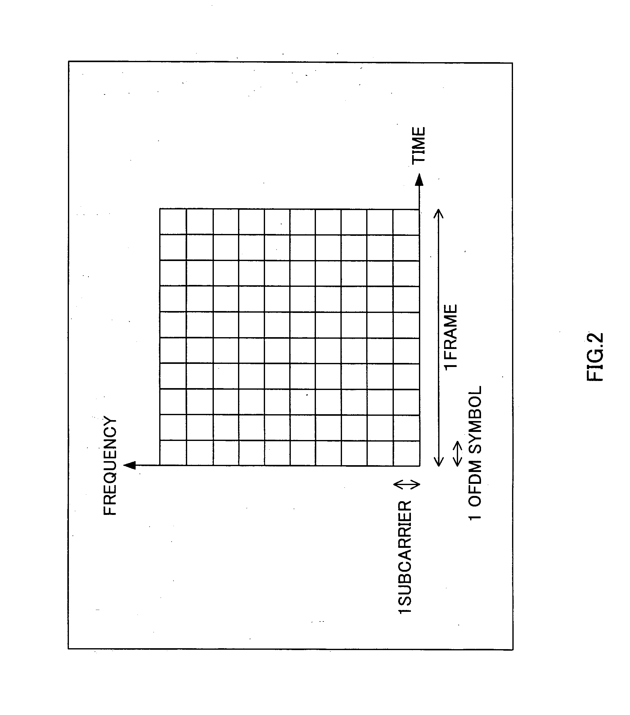
[0034]FIG. 2 shows an OFDM signal consisting of a total of 100 symbols as 1 frame; 10 symbols in the time axis direction and 10 symbols in the frequency axis direction. Embodiment 1 will be explained more specifically by taking a case where this OFDM signal having 100 symbols as 1 frame is transmitted and received as an example.

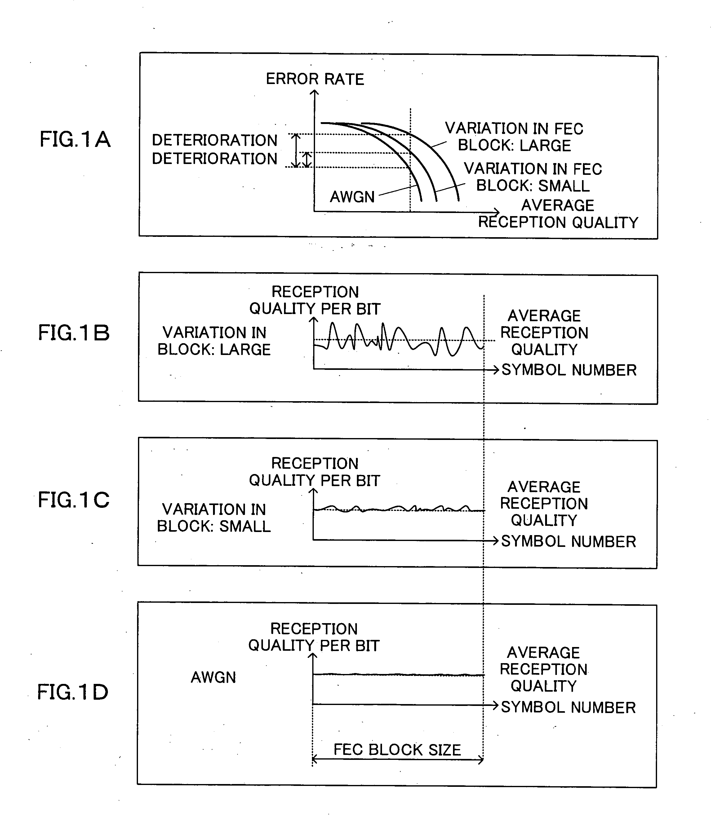
[0035] If a code block generated by carrying out error correcting coding processing on the OFDM signal is assumed to consist of 10 symbols, it is possible to arrange 10 code blocks in 1 frame. This embodiment analyzes SNR variation (reception state) of each symbol in 1 frame of an OFDM signal which has been actually received by a receiver through a propagation path by observing Doppler frequency and delay profile and adjusts the arrangement of code blocks in 1 frame of OFDM signals to be transmitted subsequently based on the analysis result and thereby reduces SNR variations per symbol of code blocks.

[0036] The SNR of each symbol fluctuates drastically in t...

embodiment 2

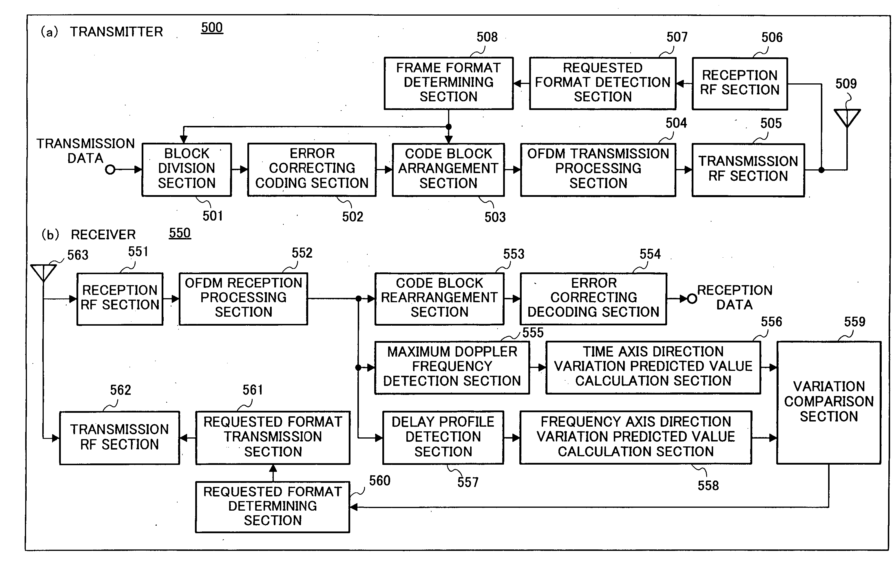
[0055]FIG. 8 is a block diagram showing the configuration of a receiver used for a multicarrier communication method according to Embodiment 2. In this embodiment, during one-to-one OFDM communication, the receiver predicts the amount of SNR variation per symbol in code blocks of an OFDM signal based on its SIR (Signal-to-Interference power Ratio) and determine the arrangement of the code blocks.

[0056] Hereinafter, the multicarrier communication method and a receiver used for the method according to this embodiment will be explained with reference to the attached drawings as appropriate, but components having functions similar to those of the components shown in Embodiment 1 are assigned the same reference numerals and explanations thereof will be omitted.

[0057] Receiver 750 corresponds to receiver 550 provided with reception SIR per symbol prediction section 701, 1×10 mapping SIR distribution calculation section 702, 5×2 mapping SIR distribution calculation section 703, 10×1 mapp...

embodiment 3

[0063]FIG. 9 is a block diagram showing the configuration of a multicarrier communication apparatus according to Embodiment 3. In this embodiment, during one-to-one OFDM communication, a receiver does not analyze a reception state of an OFDM signal and sends information on the reception state to a transmitter, and then the transmitter analyzes the reception state based on the information and thereby determines an arrangement of code blocks in 1 frame of the OFDM signal.

[0064] Hereinafter, the multicarrier communication method and the communication apparatus thereof will be explained with reference to the accompanying drawings as appropriate, but components having the same functions as those of the components shown in Embodiment 1 are assigned the same reference numerals and explanations thereof will be omitted.

[0065] Transmitter 800 corresponds to transmitter 500 provided with channel information detection section 807 instead of requested format detection section 507. Channel info...


PUM


Abstract

A multicarrier communication method and a multicarrier communication apparatus used for the method for adjusting the arrangement in code block units according to the actual reception state of the multicarrier signal, when arranging code blocks generated through error correcting coding processing not only in the time axis direction but also in the frequency axis direction in order to improve an error correction rate of a multicarrier signal. The method according to the present invention includes a coding processing step of carrying out error correcting coding processing on a multicarrier signal, a transmission step of transmitting the multicarrier signal subjected to the error correcting coding processing, a reception step of receiving the multicarrier signal transmitted, an analysis step of analyzing a reception state based on the multicarrier signal received and an arrangement adjusting step of adjusting the arrangement of code blocks generated through the error correcting coding processing according to the analysis result in the analysis step.

Description

TECHNICAL FIELD [0001] The present invention relates to a multicarrier communication method and a multicarrier communication apparatus. BACKGROUND ART [0002] Conventionally, a technology for enhancing reception performance by carrying out two-dimensional spreading in an OFDM (Orthogonal Frequency Division Multiplexing) / CDMA (Code Division Multiple Access) communication system is described, for example, in Unexamined Japanese Patent Publication No. 2000-332724. The technology described in this Unexamined Japanese Patent Publication No. 2000-332724 arranges spreading chips not only in the time axis direction but also in the frequency axis direction in an OFDM / CDMA communication system so as to reduce inter-code interference caused by loss of orthogonality between the spreading codes. [0003] However, the technology described in Unexamined Japanese Patent Publication No. 2000-332724 is intended to prevent loss of orthogonality between spreading codes in the OFDM / CDMA communication syste...

Claims


Application Information

Patent Timeline
Patent Type & Authority Applications(United States)
IPC IPC(8): H04K1/10H04J11/00H04L1/00H04L27/26
CPCH04L1/0006H04L1/0009H04L1/0026H04L1/0041H04L1/0059H04L1/0066H04L27/2602H04B17/364H04B17/336
Inventor MIYOSHI, KENICHICHENG, JUN
Owner OPTIS WIRELESS TECH LLC
Why Eureka
Try Eureka