Electric fan system for vehicle

Inactive Publication Date: 2006-06-08
DENSO CORP
View PDF4 Cites 37 Cited by
  • Summary
  • Abstract
  • Description
  • Claims
  • Application Information

AI Technical Summary

Benefits of technology

[0016] A first object of the present invention is to provide an electric fan system for a vehicle ena

Problems solved by technology

However, in this case, by employing an electric motor with a large rated capacity, there is a possibility of inviting not only an increase in cost, but also an increase in weight.
Further, in an electric motor for an electric fan, it is known to employ a brushless motor so as to extend the lifetime of the electric motor, but when the dimension of the radiator in the vehicle width direction (left-right direction of vehicle) is larger than the dimension of the rotor of the electric fan in the vehicle width direction, with just a single electric fan, the distribution of air blown to the radiator would deteriorate and parts of the radiator where cooling air is not blown would end up arising thereby inviting a drop in the cooling efficiency of the radiator and in turn deterioration of the fuel economy.
As oppo

Method used


Image

  • Electric fan system for vehicle
  • Electric fan system for vehicle
  • Electric fan system for vehicle

Examples


Example

First Embodiment

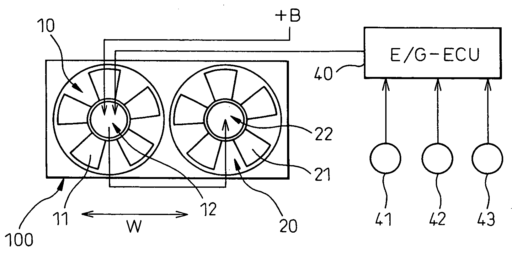
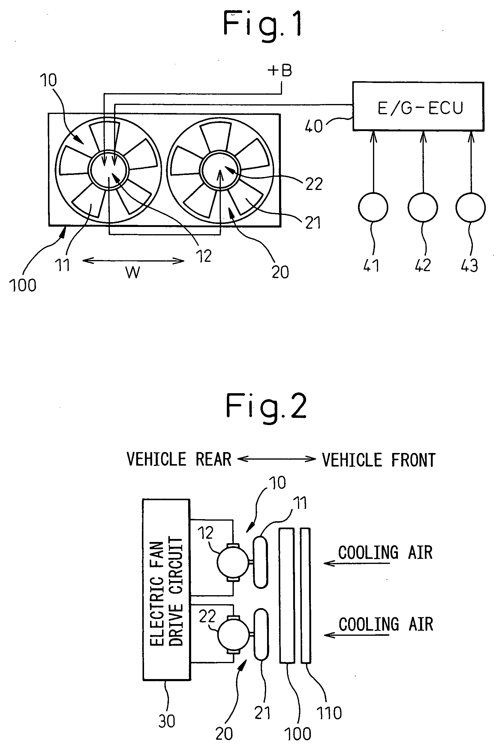
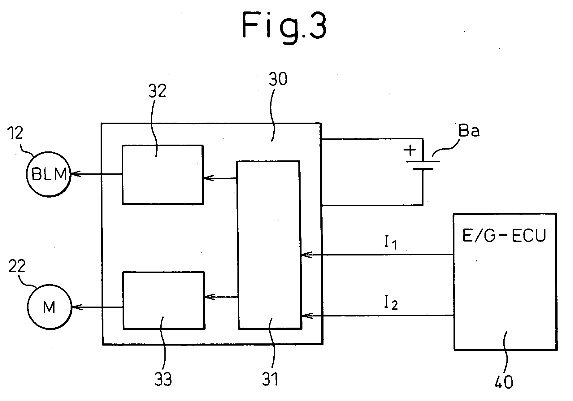
[0049]FIG. 1 to FIG. 4 show the configuration of an electric fan system for a vehicle according to a first embodiment of the present invention. FIG. 1 and FIG. 2 are schematic views of the configuration of the electric fan system for a vehicle.

[0050] The electric fan system for a vehicle is provided inside an engine compartment of the vehicle, as shown in FIG. 1, with first and second electric fans 10 and 20 comprised of axial flow fans. The first electric fan 10 is comprised of a rotor 11 and a brushless motor 12 for driving rotation of the rotor 11, while the second electric fan 20 is comprised of a rotor 21 and a brush motor (DC motor) 22 for driving rotation of the rotor 21.

[0051] The first and second electric fans 10 and 20 function to circulate cooling air to the radiator 100 and the condenser 110 forming the heat exchange unit so as to cool the radiator 100 and the condenser 110.

[0052] Further, the radiator 100 and the condenser 110 are arranged in the eng...

Example

Second Embodiment

[0094]FIG. 10 shows the configuration of an electric fan system for a vehicle according to a second embodiment of the present invention. FIG. 10 is a view showing the partial configuration in the engine compartment of a vehicle.

[0095] The electric fan system for a vehicle is provided with, as shown in FIG. 10, electric fans 10 and 20. The electric fans 10 and 10 are arranged inside the engine compartment in the front-rear direction at the front side of a water-cooled engine 300. The electric fan 10 is the same as that shown in FIG. 1 and is comprised of a rotor and a brushless motor for driving rotation of the rotor, while the electric fan 20 is comprised of a rotor and a brush motor for driving rotation of the rotor.

[0096] On the other hand, at the front side of the electric fans 10 and 20, a radiator 100 and a condenser 110 are arranged in parallel in the front-rear direction. The electric fans 10 and 20 function to send cooling air to the radiator 100 and the ...


PUM


Abstract

An electric fan system for a vehicle including two electric fans (10, 20) arranged in parallel in a vehicle width direction so as to blow cooling air to a radiator (100) and a condenser (110), wherein the electric fans are driven by a brushless motor (12) and a brush motor (22), a first drive voltage V1 for driving the brushless motor is set so as to increase in accordance with an increase of a water temperature (Tw) of the radiator or a coolant pressure (Pc) of the condenser, and simultaneously a second drive voltage V2 for driving the brush motor is set so as to increase monotonously as a value lower than the first drive voltage, whereby the two electric fans can operate simultaneously at all times, unevenness of the distribution of the flow rate can be reduced, and the drive voltage of the brush motor is reduced, so the lifetime can be extended and, further, provision is made of an electronic control unit (40a) for preferentially operating the electric fan (10) driven by the brushless motor over the electric fan (20) driven by the brush motor based on the temperature of the engine cooling water and the electric fan (10) driven by the brushless motor is designed to cool by cooling air other vehicle-mounted parts besides the radiator (100) and the condenser (110), specifically for example the ECU box (410).

Description

CROSS REFERENCES TO RELATED APPLICATIONS [0001] This application is based upon and claims priorities of Japanese Patent Application No. 2004-352743, filed in the Japan Patent Office on Dec. 6, 2004, and Japanese Patent Application No. 2004-376269, filed in the Japan Patent Office on Dec. 27, 2004, the contents being incorporated herein by reference. BACKGROUND OF THE INVENTION [0002] 1. Field of the Invention [0003] The present invention relates to an electric fan system for a vehicle which uses an electric fan to generate cooling air. [0004] 2. Description of the Related Art [0005] In the past, as an electric fan system for a vehicle, there has been one which used an electric fan to circulate cooling air to a radiator for cooling engine cooling water and a condenser for vehicle air-conditioning so as cool the radiator and condenser. [0006] In general, in a taxi, bus, or other vehicle with a high frequency of use of the electric fan, a sufficient fan capacity, rectification of the d...

Claims


Application Information

Patent Timeline
IPC IPC(8): F04B49/10F04B17/00
CPCF01P7/048F01P2005/025F01P2005/046F01P2025/04F01P2025/46F01P2060/14F04D27/004Y02B30/70
Inventor IWASAKI, TAKAHIROODA, SHINICHI
Owner DENSO CORP
Why Eureka
Try Eureka