
High-voltage wire connecting structure and high-voltage wire connecting method

a high-voltage wire and connecting structure technology, applied in the direction of connection insulation, coupling device connection, contact member penetration/cutting insulation/cable strand, etc., can solve the problem of low productivity, achieve high productivity, short processing time, and highly reliable electrical contact

Inactive Publication Date: 2006-06-08
YAZAKI CORP
View PDF6 Cites 40 Cited by
  • Summary
  • Abstract
  • Description
  • Claims
  • Application Information

AI Technical Summary

Benefits of technology

The present invention provides a high-voltage wire connecting structure and method that can securely connect two wires together with a smaller number of parts. The conductor of the high-voltage wire is formed into a flat plate-like terminal, while the conductor of the mating connecting member is also formed into a flat plate-like terminal. The two terminals are then connected together by melt connection means, which is sealed by a sealing material having insulating and water-stop properties. This structure can achieve a highly-reliable electrically-contacted condition and waterproof performance with a smaller number of parts. The sealing material can be a hot-melt adhesive, which has rapid curing and high productivity.

Problems solved by technology

Furthermore, in the case of effecting the potting by the epoxy resin or the silicone resin, it took much time for the molten resin to be cured, so that the productivity was low.

Method used


Image

  • High-voltage wire connecting structure and high-voltage wire connecting method
  • High-voltage wire connecting structure and high-voltage wire connecting method
  • High-voltage wire connecting structure and high-voltage wire connecting method

Examples


Embodiment Construction

[0022] A preferred embodiment of the present invention will now be described with reference to the drawings.

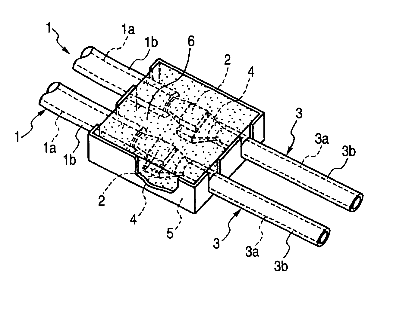
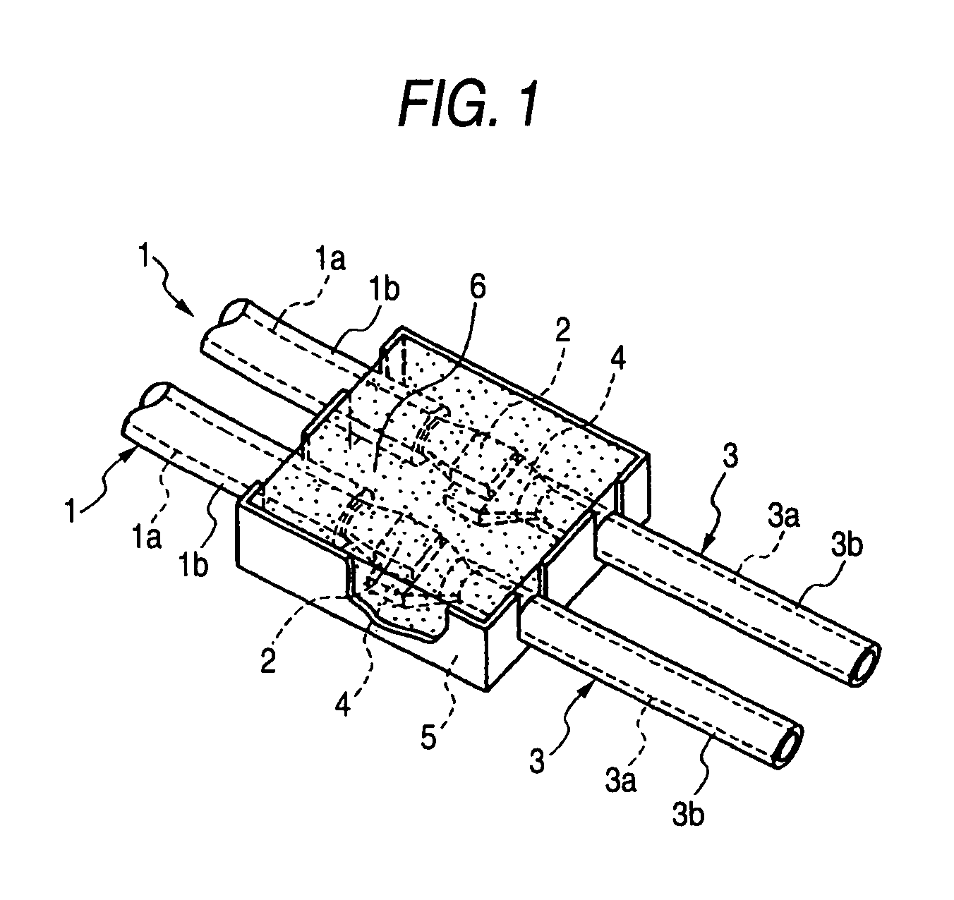
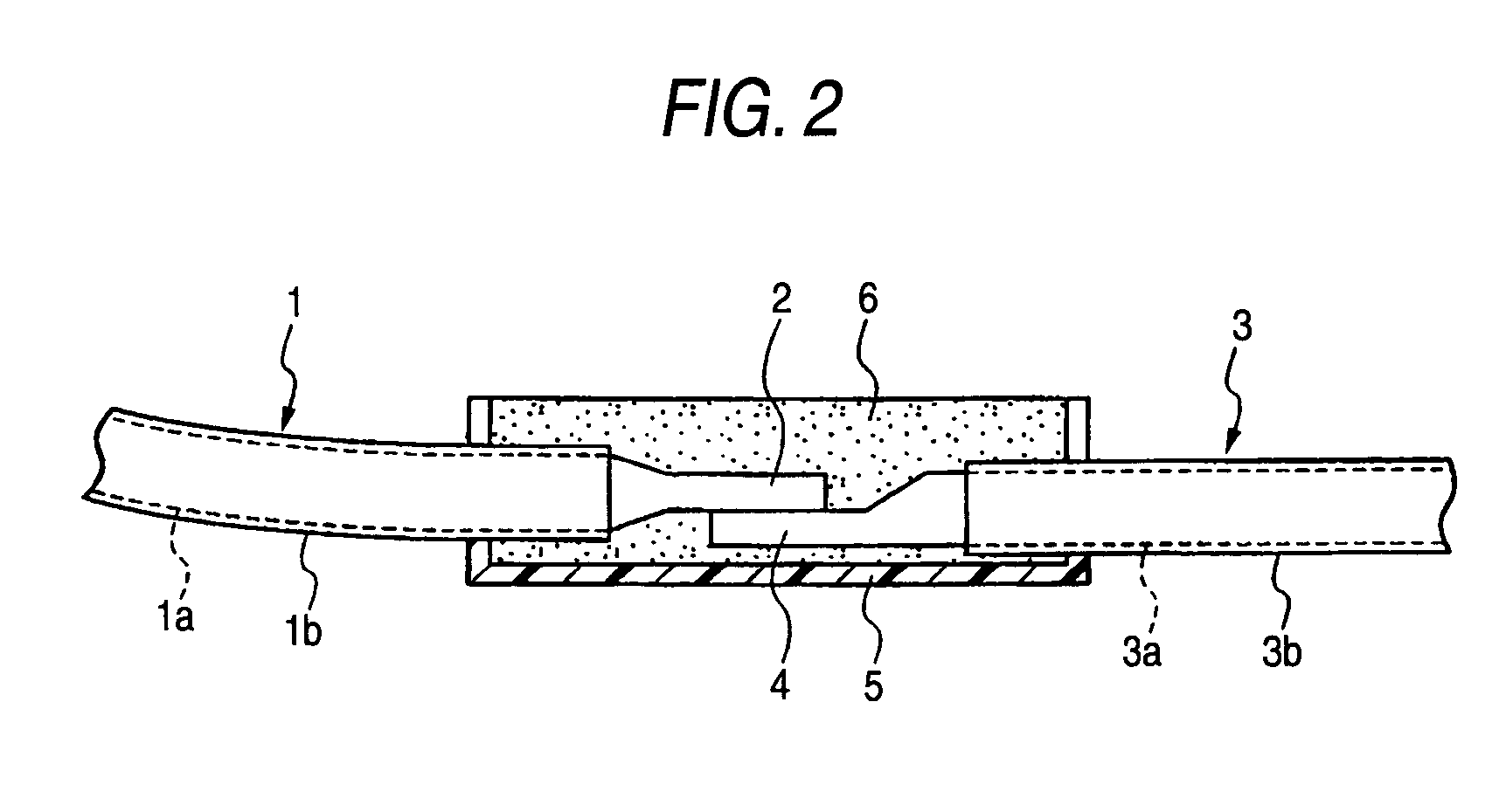
[0023] As shown in FIGS. 1 and 2, each of the two high-voltage wires 1 and 1 comprises the conductor 1a composed of a number of fine conductor wires twisted together, and a waterproof sheath 1b covering an outer periphery of the conductor 1a. The sheath 1b is removed from an end portion of the high-voltage wire 1, thereby exposing the conductor 1a. The exposed end portion of the conductor 1a is formed or processed by heat and pressure (using a thermocompression bonding apparatus or the like) into a flat plate-like terminal 2 of an integral construction.

[0024] Like the high-voltage wires 1, each of two other high-voltage wires 3 and 3 (serving as mating connecting members) comprises a conductor 3a composed of a number of fine conductor wires twisted together, and a waterproof sheath 3b covering an outer periphery of the conductor 3a. The sheath 3b is removed from an end porti...


PUM


Abstract

A portion of a conductor 1a of each high-voltage wire, exposed by removing an insulating sheath 1b, is formed into a flat plate-like terminal 2 of an integral construction. A portion of a conductor 3a of each of the other high-voltage wires 3, exposed from an insulating sheath 3b, is formed into a flat plate-like terminal 4. Each mating pair of flat plate-like terminals 2 and 4 are connected together by welding or melt adhesion, and are received within an insulating casing 5, and are sealed by a hot-melt adhesive 6 filled in the insulating casing 5.

Description

BACKGROUND OF THE INVENTION [0001] 1. Field of the Invention [0002] This invention relates to a high-voltage wire connecting structure and a high-voltage wire connecting method, in which a conductor, composed of a number of conductor wires, is connected to a conductor of a mating connecting member, and besides the waterproofness of the connected portions is secured. [0003] 2. Related Art [0004] For example, in the case of connecting a high-voltage wire, used in electric wiring of a vehicle, to a mating connecting member (e.g., another high-voltage wire), it is necessary to provide a structure by which an electrically-contacted condition of the connected portions can be kept good even upon application of vibrations or others. [0005]FIG. 5 shows one conventional high-voltage wire connecting structure. As shown in FIG. 5, a male terminal 51 (which is provided within a connector) is connected to an end portion of a conductor of a high-voltage wire 50. A female terminal 52 (which is prov...

Claims


Application Information

Patent Timeline
Patent Type & Authority Applications(United States)
IPC IPC(8): H01R4/24
CPCH01R4/70H01R13/5216H01R13/53H01R43/0207H01R43/0214
Inventor ICHIKAWA, HIDEHIROHASHIZAWA, SHIGEMI
Owner YAZAKI CORP
Learn More