Detection of derailment by determining the rate of fall

a technology of derailment and rate of fall, which is applied in the direction of vehicle position/course/altitude control, process and machine control, instruments, etc., can solve the problems of slow acceleration changes, inability to acquire, and insufficient strength of sturdy sensors to measure acceleration proportions on rail vehicles. , to achieve the effect of improving signal analysis, eliminating jamming parts, and increasing the sturdiness of the method

Active Publication Date: 2006-06-08
SIEMENS MOBILITY AUSTRIA GMBH
View PDF14 Cites 16 Cited by
  • Summary
  • Abstract
  • Description
  • Claims
  • Application Information

AI Technical Summary

Benefits of technology

[0014] In a preferred embodiment of the invention, the acceleration signal is generated in the area of the axle bearing. Low-frequency jamming portions, contained in the acceleration signal, are eliminated prior to integration in order to improve the signal analysis and to increase the sturdiness of the method against the influence of jamming. A high-pass filter is used advantageously to eliminate the jamming portions.

Problems solved by technology

Sensors that can measure the proportion of acceleration are not sturdy enough for use on rail vehicles.
Sturdy sensors, however, cannot measure the proportion; they have a lower boundary frequency.
Slow changes in acceleration thus cannot be acquired.
There is one disadvantage connected with this known embodiment in that the double integration brings about a very poor signal-to-noise ratio.
Stiff requirements are established for the analysis electronics by double integration, as a result of which, the production costs can turn out to be high.
Furthermore, using the known method or system, there can be delays in the recognition of derailed states due to the required expensive analysis electronics.

Method used


Image

  • Detection of derailment by determining the rate of fall
  • Detection of derailment by determining the rate of fall
  • Detection of derailment by determining the rate of fall

Examples


Embodiment Construction

[0025] In the drawings, like numerals indicate like elements throughout. In the drawings, like numerals indicate like elements throughout. Certain terminology is used herein for convenience only and is not to be taken as a limitation on the present invention. The embodiments illustrated below are not intended to be exhaustive or to limit the invention to the precise form disclosed. These embodiments are chosen and described to best explain the principle of the invention and its application and practical use and to enable others skilled in the art to best utilize the invention.

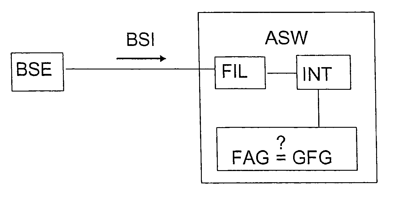
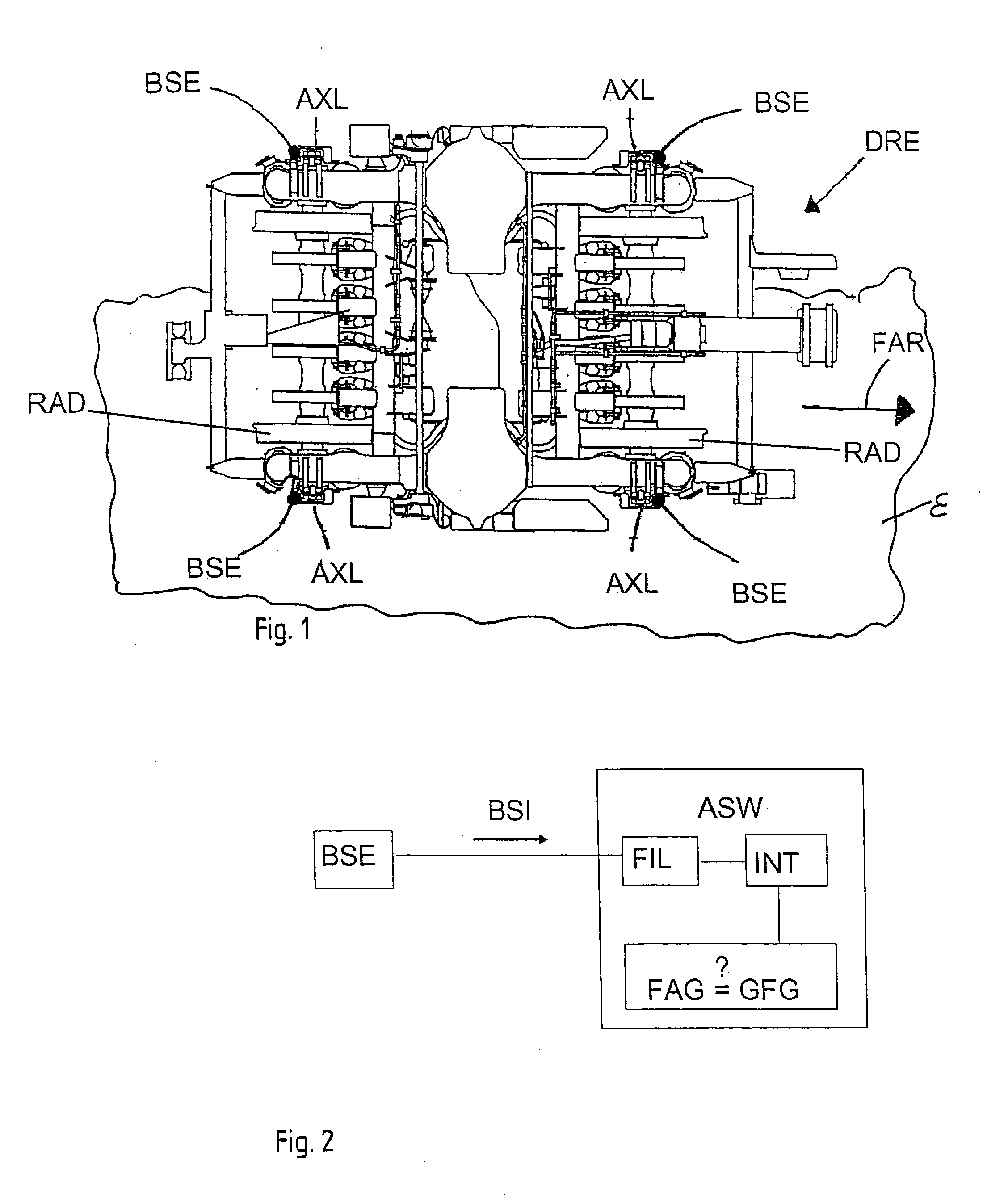
[0026] According to FIG. 1, to implement the invention-based method for the purpose of recognizing a derailed state of a rail vehicle, an acceleration signal is generated in the area of a truck DRE of the rail vehicle. For this purpose, an invention-based device has an acceleration sensor BSE that can be arranged on an axle bearing AXL of a wheel RAD or wheel set of the rail vehicle. An acceleration sensor BSE...


PUM


Abstract

A method and a device for the recognition of a derailment state of a wheel (RAD) of a rail vehicle. The acceleration of the wheel (RAD) is measured perpendicularly to a rail plane (ε) with at least one acceleration sensor (SEN), whereby from an acceleration signal (BSI) generated by the acceleration sensor (SEN) by means of simple integration (INT) over a time window of predeterminable magnitude, one determines a fall speed (FAG) of the wheel (RAD) in the direction of the rail plane (ε), and whereby on the basis of the determined fall speed (FAG), one examines whether a derailed state exists.

Description

CROSS-REFERENCE TO RELATED APPLICATIONS [0001] This application claims priority from PCT Application No. PCT / AT04 / 000173 filed May 17, 2004 which claims priority from Austrian Patent Application No. A 746 / 2003 filed May 15, 2003.FIELD OF THE INVENTION [0002] This invention relates to a method for recognizing a derailment state of a wheel set of a rail vehicle, where the acceleration of the wheel set is measured perpendicularly to a rail plane with an acceleration sensor. BACKGROUND OF THE INVENTION [0003] The invention furthermore relates to a device for recognizing a derailment state of a wheel of a rail vehicle, which displays at least one acceleration sensor for the acquisition of the acceleration of the wheel perpendicularly to a rail plane, where the acceleration sensor is fitted out with an analysis unit for the analysis of an acceleration signal generated by the acceleration sensor. [0004] A wheel or wheel set of a rail vehicle, for example, can be subjected to quasistatic ac...

Claims


Application Information

Patent Timeline
Patent Type & Authority Applications(United States)
IPC IPC(8): G05D1/00G06F17/00B61F9/00B61K13/00
CPCB61F9/005B61K13/00B61L23/00
Inventor LUEGER, GERHARDKITZMULLER, CHRISTIANSALZGEBER, GERARDSCHMEJA, MICHAEL
Owner SIEMENS MOBILITY AUSTRIA GMBH
Why Eureka
Try Eureka