Optical network for bi-directional wireless communication
Active Publication Date: 2006-06-08
SAMSUNG ELECTRONICS CO LTD
View PDF11 Cites 36 Cited by
Summary
Abstract
Description
Claims
Application Information
AI Technical Summary
This helps you quickly interpret patents by identifying the three key elements:
Problems solved by technology
Method used
Benefits of technology
Benefits of technology
[0010] Another aspect of the present invention relates to a method for realizing continuous service by reducing bit rates of the provided video data, even when network condition gets deteriorated due to a congestion of service requests from the many subscribers.
Problems solved by technology
In the conventional video data transmission as mentioned above, losses and delays of the IP networks exert a detrimental influence on streaming services of multimedia data.
Especially, the burst transmission characteristic of the IP network can severely hinder the QoS (Quality of Service) of multimedia data streaming services when providing the real time broadcast through the IP network.
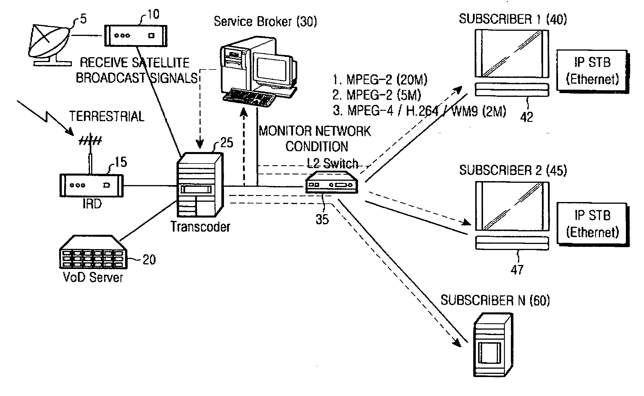
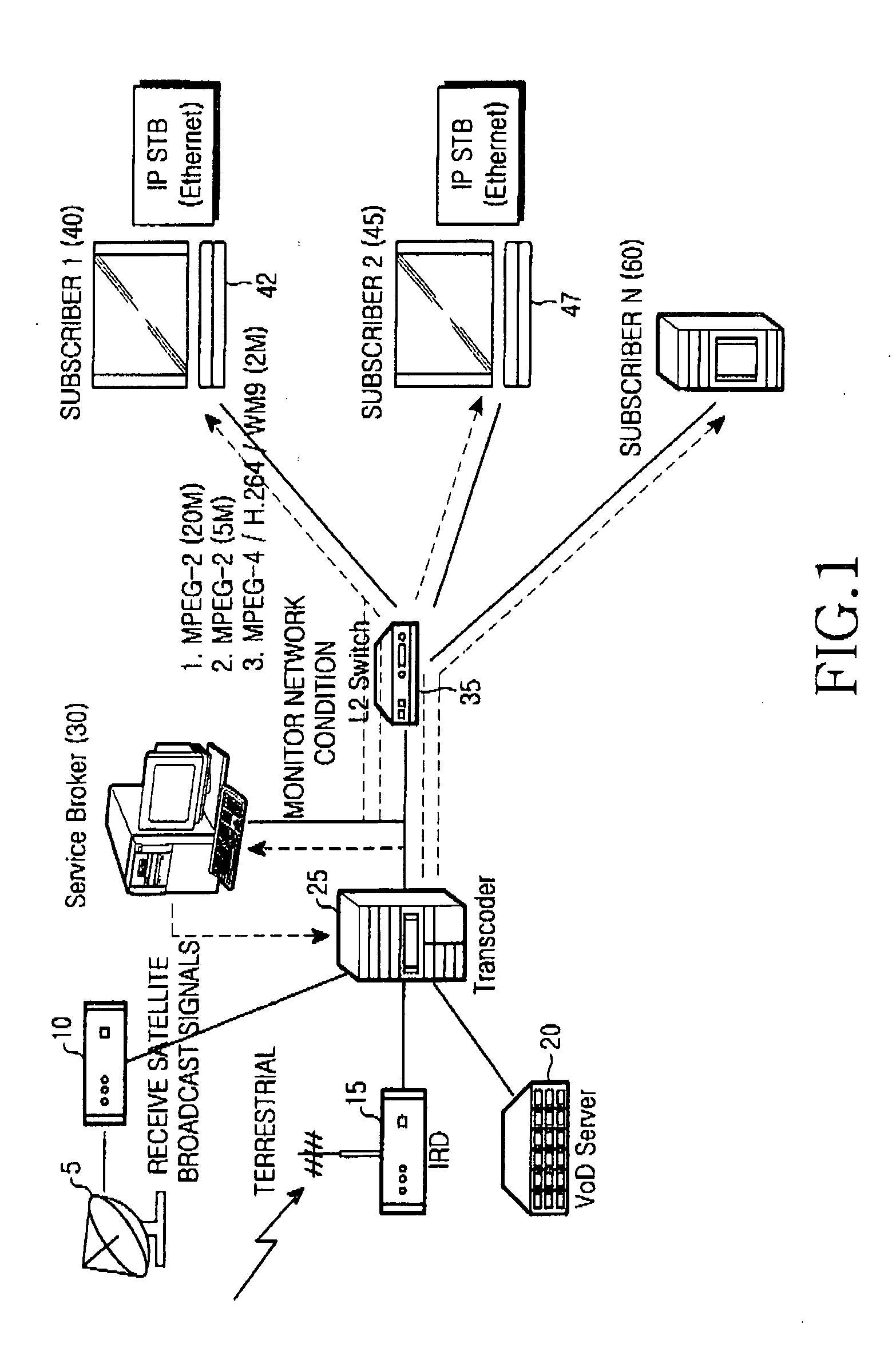
For example, when a subscriber watches TV which receives a 20 Mbps HD broadcast signal of the highest QoS via a conventional network system, if the network system performance has deteriorated (due to a congestion of service requests from subscribers), the subscriber cannot continue to receive the HD broadcast service via the TV because there are no means for overcoming or curing properly the changed condition of video transmission operation.
Method used
Image
Click on the blue label to locate the original text in one second.
Reading with bidirectional positioning of images and text.
Examples
first embodiment
[0043]FIG. 4 is a view for explaining insertion of the transcoding point information in a transport packet stream, according to the present invention.
[0044] The MPEG-2 system among the digital broadcast data types adopts a packet division scheme that is used in a TDM (Time Division Multiplexing) scheme. In this scheme, video and audio bit streams are first divided into a proper length of bit stream called a packet (hereinafter referred to as “PES”: Packetized Elementary Stream), respectively. The PES packet has a higher length limit of 64 KB for adapting various applications. Also each PES packet may have fixed or variable length if necessary, and may further have variable transmission speed. Furthermore, the PES packets can be transmitted intermittently.
[0045] As mentioned above, all the PES are multiplexed into a single bit stream to be a program stream (PS) or a transport stream (TS). The program stream is a packet used for the MPEG-1 system and the transport stream is used for ...
second embodiment
[0047]FIG. 5 is a view for explaining insertion of the transcoding point information in a private section, according to the present invention.
[0048] The second embodiment is a method in which the transcoding point information is inserted into a private section. The private section is a flexibly-defined standard for enabling to transmit user-defined data accompanied with the transport streams (The standard is “MPEG-2 system standard ISO / IEC13818-1).
[0049] A kind of program guide information or service information is divided into sections each of which a table_id for identification is allocated to, respectively. Among the table_ids, Ox40 to Ox7F and Ox80 to OxBF are in the range of the user private section.
[0050] For example, in both cases of an ATSC of USA type and a DVB of EU type using MPEG-2 system, an unique system information is inserted into the user private section to be transmitted therewith. As shown in FIG. 5, the private section includes several fields. The transcoding p...
third embodiment
[0051]FIG. 6 is a view for explaining insertion of the transcoding point information in a packet header, according to the present invention.
[0052] The third embodiment is a method in which the transcoding point information is inserted into a header of the PES packet. Specifically, an optional PES header has optional fields as well as other elements. The optional fields have optional fields PES which have 5 flags and optional fields which have PES private data into which the transcoding point information is inserted.
[0053] As mentioned in FIGS. 4 to 6, the transcoding point information can be inserted into each of the private sections or fields of the packet header. The receiver that has received the packet including transcoding point formation uses the transcoding point information from the packet.
[0054]FIG. 7 is a flow chart for explaining a process for extracting the transcoding point information in a receiver according to an embodiment of the present invention.
[0055] The recei...
PUM
Abstract
A method for transmitting video data to the users via a network in a transcoder of an image processingsystem including a storage media having a predetermined amount of storage area is disclosed. The method includes the steps of storing in the storage media, the video data provided based on the corresponding services, monitoring a traffic condition of the network to determine if transcoding is necessary; transmitting the stored video data to the corresponding users, respectively, via the network, when the transcoding is not necessary; and transcoding the stored video data to transmit the video data to the corresponding users, respectively, when the transcoding is necessary. The video data provided is based on the corresponding services includes image information having the highest quality of service from a content provider.
Description
CLAIM OF PRIORITY [0001] This application claims priority to an application entitled “TRANSCODING METHOD FOR CONTINUOUS VIDEO DISPLAY,” filed in the Korean Intellectual Property Office on Dec. 7, 2004 and assigned Serial No. 2004-102388, the contents of which are hereby incorporated by reference. BACKGROUND OF THE INVENTION [0002] 1. Field of the Invention [0003] The present invention relates to a network transmission method, more particularly to a transcoding method for continuous video display regardless of bandwidth changes in a network. [0004] 2. Description of the Related Art [0005] Real time broadcasts using an IP networks are commercially available. [0006] When executing a conventional video data transmission, video / audio data should be transmitted in a compressed form because of large volume of data generally involved. Real time transmission characteristics are very important to various application services. Such application services include for example, a digital broadcast,...
Claims
Application Information
Patent Timeline
Application Date:The date an application was filed.
Publication Date:The date a patent or application was officially published.
First Publication Date:The earliest publication date of a patent with the same application number.
Issue Date:Publication date of the patent grant document.
PCT Entry Date:The Entry date of PCT National Phase.
Estimated Expiry Date:The statutory expiry date of a patent right according to the Patent Law, and it is the longest term of protection that the patent right can achieve without the termination of the patent right due to other reasons(Term extension factor has been taken into account ).
Invalid Date:Actual expiry date is based on effective date or publication date of legal transaction data of invalid patent.

