Continuous flow grain dryer

a continuous flow, grain dryer technology, applied in drying, furnace types, light and heating equipment, etc., can solve the problems of high energy consumption, affecting the quality of grain, and increasing the risk of fire and explosion in the machin

Inactive Publication Date: 2006-06-15
ING MEGA
View PDF5 Cites 17 Cited by
  • Summary
  • Abstract
  • Description
  • Claims
  • Application Information

AI Technical Summary

Benefits of technology

[0011] It is therefore an object of the invention to provide a continuous flow grain dryer machine of the type comprising at least one column for containing the grain that moves downwardly along a zig-zag path and a plurality of indi

Problems solved by technology

In addition, floor diverters are provided to revert the circulating direction of the heating air, however the grain is always under the heating effect of the hot air passing through the orifices in the walls and this affects the quality of the grain that is undergoing an overheating, affecting the same by generating “fissures” and craks, for example.
In addition to the foregoing the diverting floor portions promote the accumulation of grain dust that increase the fire and explosion risk in the machine.
Also, the pressure into these dryers necessary to make the air circulate efficiently through the columns is very important and it demands high energy consumption.
While the above machines have been employed during many years as well as they are provided with large room for the introduction and circulation of drying air between the columns, the structure and constructions of these machines, with foraminous metal walls is very costly.
In addition, the grain is compacted within

Method used


Image

  • Continuous flow grain dryer
  • Continuous flow grain dryer
  • Continuous flow grain dryer

Examples


Embodiment Construction

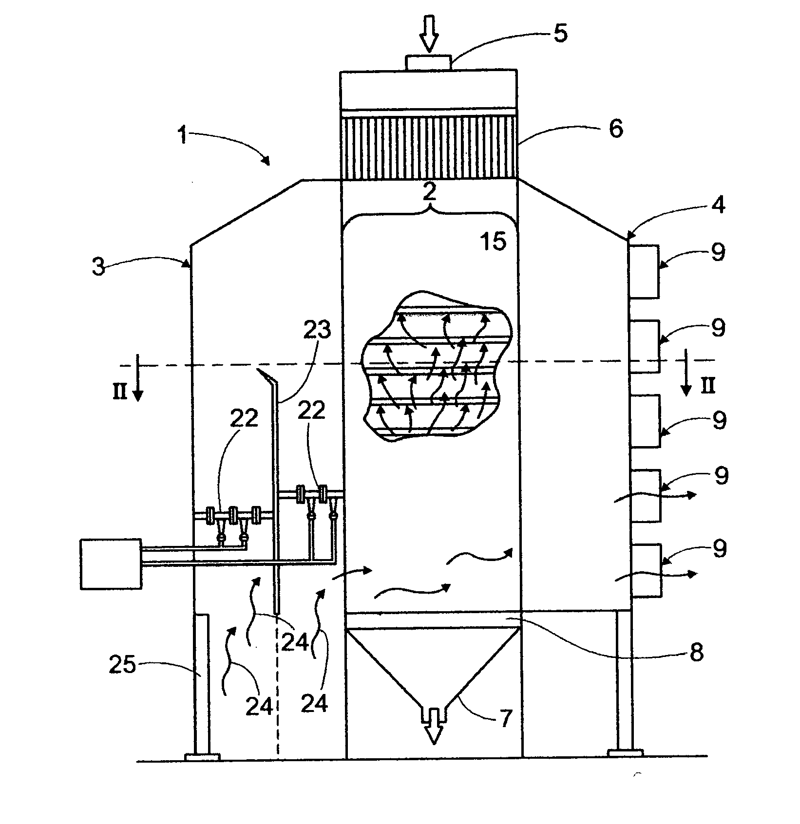
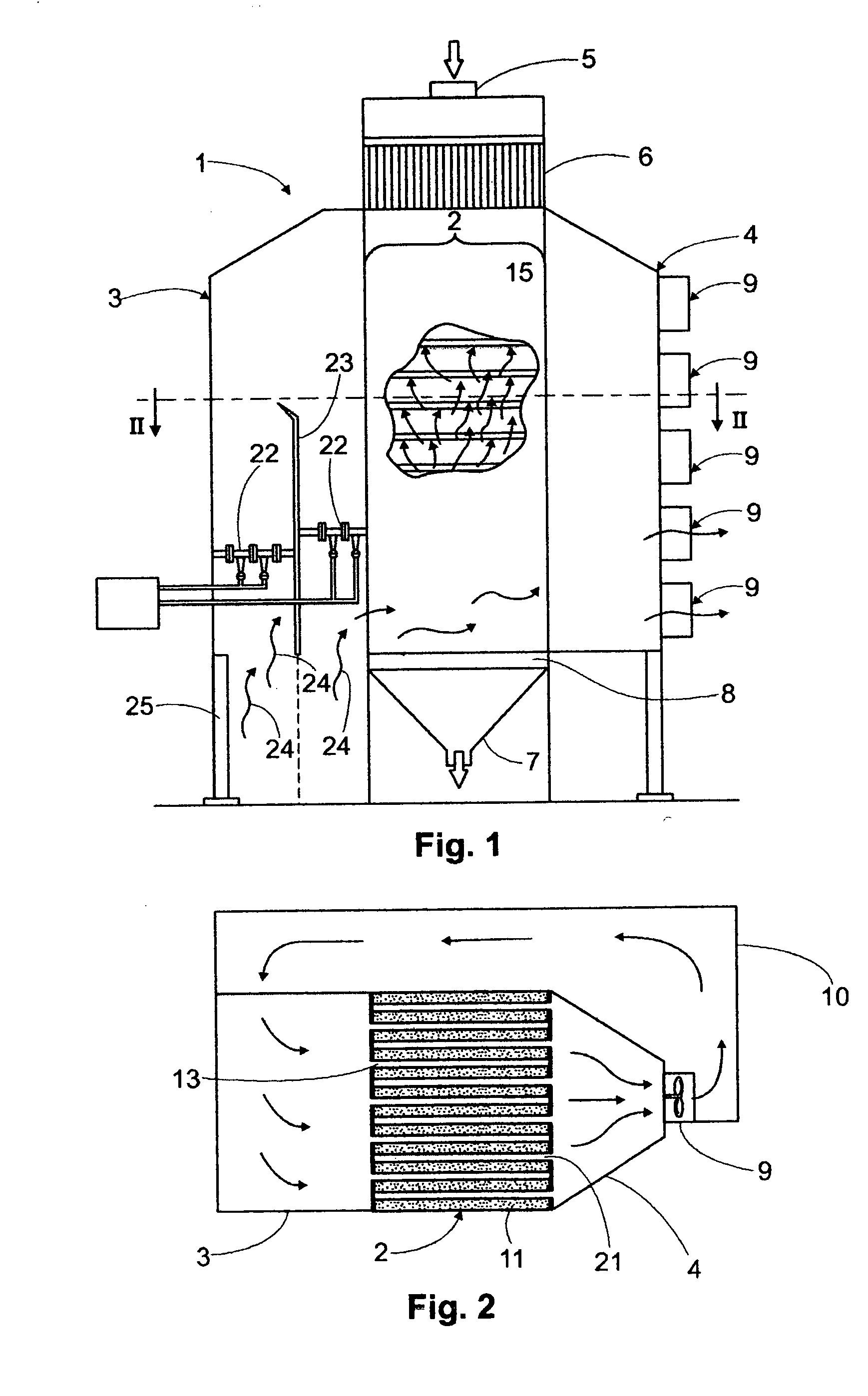
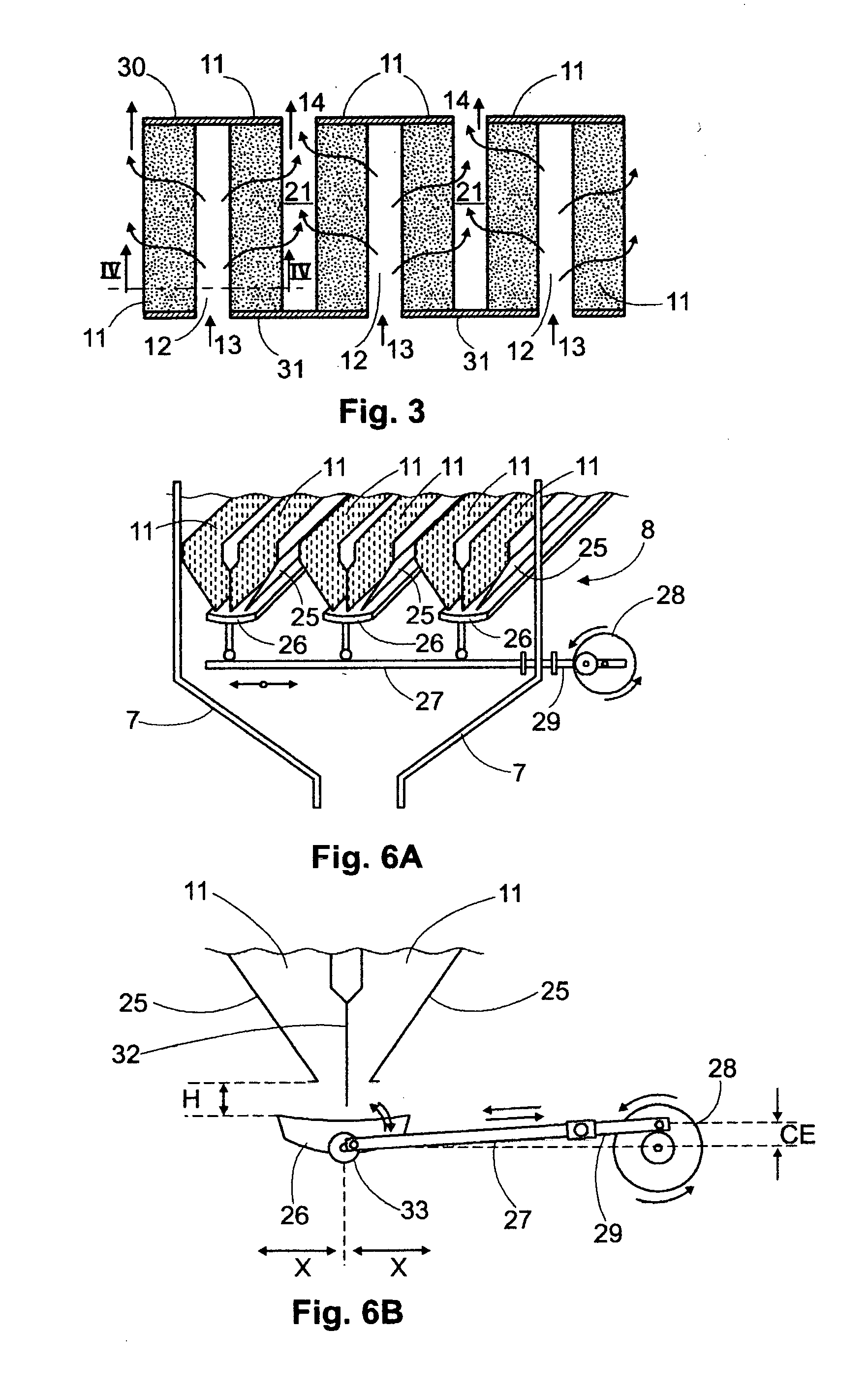
[0034] Now referring in detail to the invention, the same refers to a continuous flow grain drying machine indicated by general reference number 1, having a central body 2 for receiving and circulating the grain to be dried, a rear chamber 3 for entering hot drying air into body 2 and a leading exhausted air chamber or collector 4. Main body 2 has at an upper portion thereof a general grain inlet 5 and an adjacent downwardly located loading hopper 6 debouching into main body 2. The grain containing moisture, or wet grain, enters through inlet 5, moves downwardly through main body 2, it is dried by the hot air flowing through the mass of grain and exists the machine through a general dry grain outlet 7 at the bottom of the machine. The exiting of grain is controlled by a gate mechanism 8 better illustrated in FIGS. 6A and 6B to which reference will be made below. Air from outside is entered into chamber 3 and is heated by a plurality of burners 22 that may be operated by several fuel...


PUM


Abstract

A continuous flow grain dryer comprising a plurality of vertical columns for receiving and heating/drying grain, with each column having an inlet wall including side drying air inlets, and an opposite outlet wall including side exhausted air outlets, wherein the inlets and outlets are provided with diverters angularly extending towards a longitudinal axis of the column and defining a central clear region for permitting the free downward moving of the grain, with an air descending path being defined between an inlet and a downwardly adjacent outlet, and a tempering region being defined between a diverter and an associated opposite wall portion.

Description

BACKGROUND OF THE INVENTION [0001] 1. Field of the Invention [0002] The present invention relates to a grain dryer and more particularly to a continuous flow grain dryer of the type employed in the drying of grains for conditioning the same for several purposes, such as for consumption, for seeds, etc. The dryer is a machine having a plurality of drying columns wherein the grain is loaded at the top of the columns and the grain under drying process moves downwardly, substantially along a zig-zag pattern to exit at a bottom of the columns, with each column provided with a plurality of side inlets for receiving heated air and a plurality of outlets for exiting exhausted air already circulated through the grain in the column, and wherein the inlets and outlets are provided with diverters to define the zig-zag pattern as well as to define tempering regions for the grain and air spaced apart paths for the heating drying air. [0003] 2. Description of the Prior Art [0004] The grain dryers ...

Claims


Application Information

Patent Timeline
IPC IPC(8): F26B7/00F26B3/00
CPCF26B17/126
Inventor VALFIORANI, MARCELO NORBERTO
Owner ING MEGA
Why Eureka
Try Eureka