Electrocution animal trap with a sender

a technology of electrocution and animal trap, which is applied in the direction of animal traps, electric shock equipment, insect catchers and killers, etc., can solve the problems of not being able to deal with the trap described above, the electrocution of noxious animals is a well-known problem, and the animal touches the electrodes inevitably, so as to achieve the effect of avoiding electrocution

Inactive Publication Date: 2006-06-15
RATCO
View PDF61 Cites 47 Cited by
  • Summary
  • Abstract
  • Description
  • Claims
  • Application Information

AI Technical Summary

Problems solved by technology

The extermination of noxious animals is a well-known problem.
The inside of the trap is designed in such a way that, if an animal tries to reach the bait, the animal inevitably touches the electrodes and thereby gets electrocuted.
None of the previously described traps, however, deal with the situatio

Method used


Image

  • Electrocution animal trap with a sender
  • Electrocution animal trap with a sender
  • Electrocution animal trap with a sender

Examples


first embodiment

[0004] In a first embodiment, the above mentioned problem has been solved by the present invention by providing an electrically powered animal trap, which comprises

[0005] a set of electrodes for electrocution of the animal, and

[0006] means for communicating a surveillance signal between the trap and an external surveillance unit.

[0007] Due to the means for communicating a surveillance signal between a trap and an external unit, the keeper of the trap may know the condition of the trap without direct inspection of the trap. The trap may thus be left unattended for a long period time, where the trap keeper can rest assure, that the trap is fully operational.

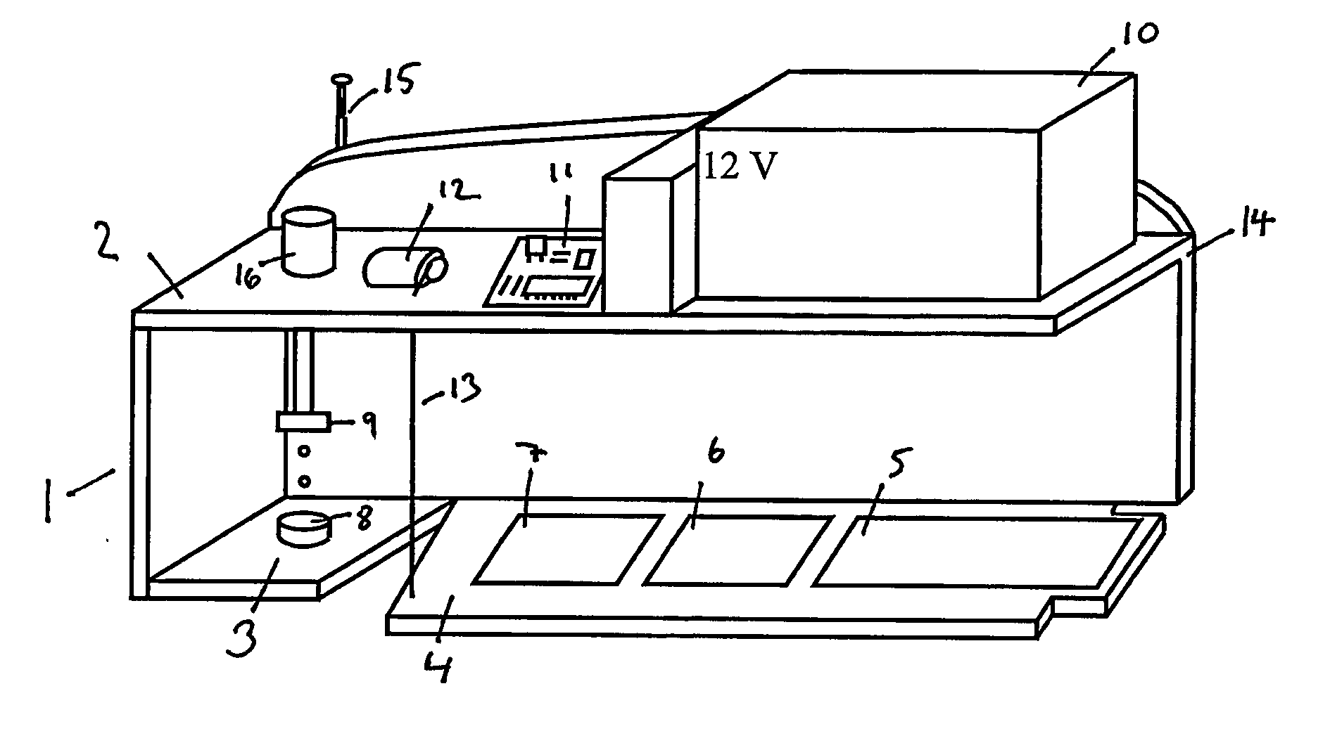
[0008] The trap may comprise a bottom section with an upwardly extending sidewall, a top section, and at least one entrance. The entrance may be either in a sidewall, in the top section of the trap, in the bottom section of the trap, or anywhere else. Upon entering the trap, the animal enters a chamber, where a bait or lure may ...

second embodiment

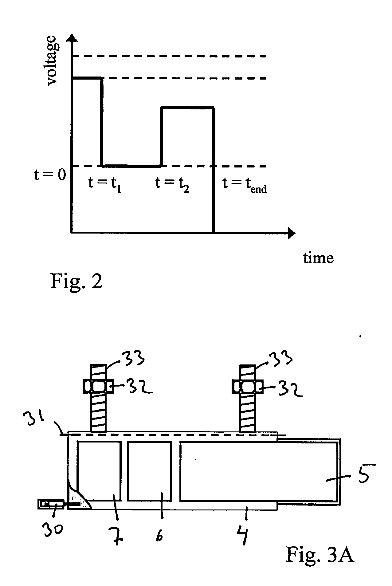
[0033]FIG. 3A shows the trapdoor 4, where instead of using a motor 11 and a string 13, the actuation of the trapdoor is an electromagnetic switch 30 adapted to open upon a signal from the electronic circuit 11. Due to the weight of the electrocuted animal, the trapdoor opens by pivoting around a pivot tap 31, and closes after release of the animal due to counter weights, here exemplified by a threaded bolt 33 and a nut 32.

third embodiment

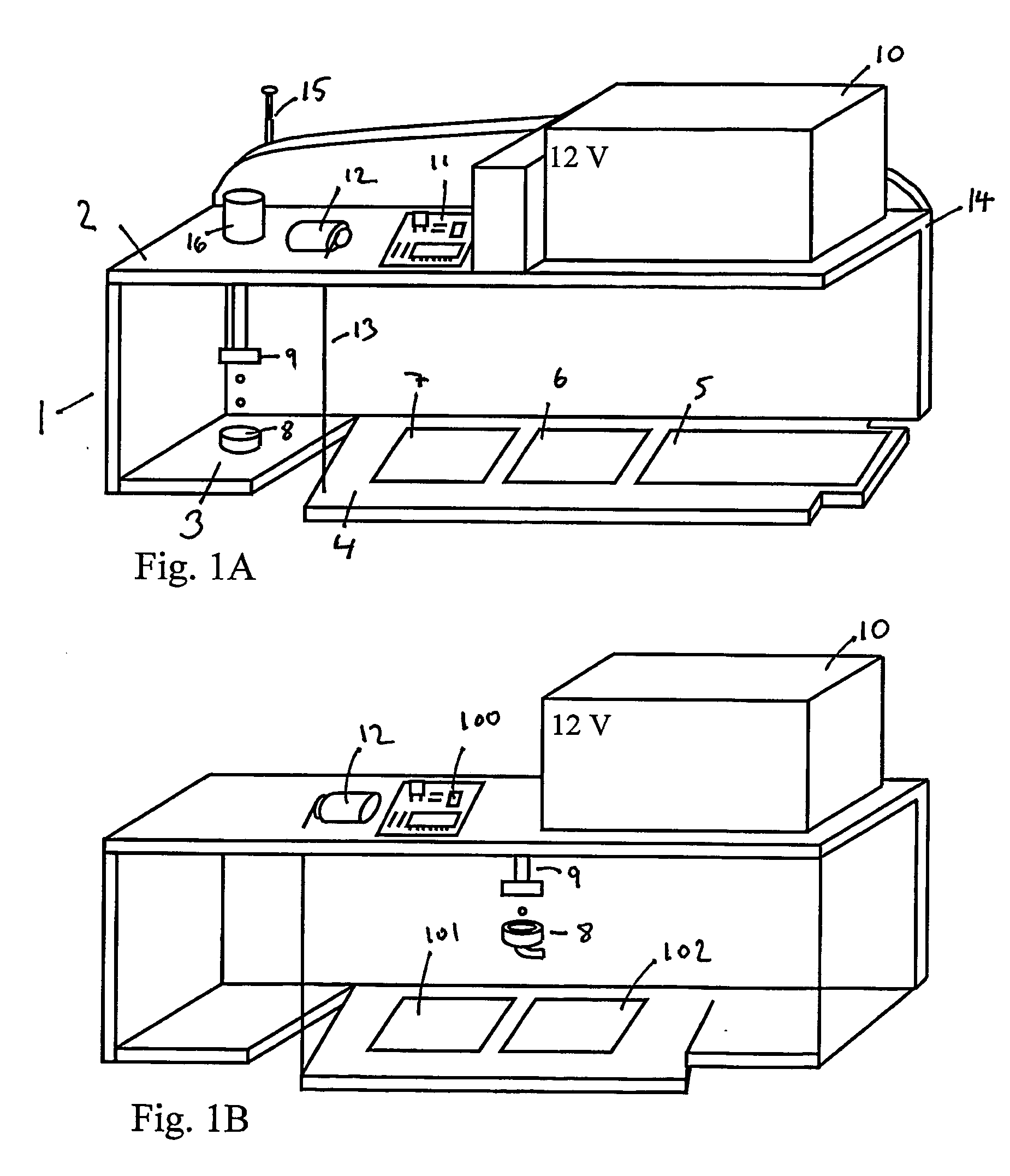
[0034] In FIG. 3B and 3C the trapdoor is shown. Here a solenoid 202 Is used to open and close the trapdoor. The solenoid may be fixed to the trap using fixation means 200 and 201. By activating the solenoid, rod 203 Is pulled into the solenoid, which through a mechanical coupling to the trapdoor, opens the trap door, as shown In FIG. 3C. Using a solenoid may e.g. increase the control of the trapdoor. For example it may be possible to shake the trapdoor to make sure the animal has fallen off, or to clear the trapdoor from debris or dirt on the electrodes or the trapdoor in general.

[0035]FIG. 4 and 5 show two examples of trap set-ups. In both Figs. the trap 20 is raised above the surroundings, and access to the trap chamber is ensured by a ramp 21. In FIG. 2 the trap is placed on top of a receptacle 22, into which the animals are dumped after the electrocution. Where FIG. 4 present a trap set-up that can be used in many different locations, e.g. a store-house, a barn or a field, FIG. ...


PUM


Abstract

An electrically powered rodent trap which includes a surveillance system for remote surveillance of the trap so that the trap may be operated without being attended to. A rodent which enters into the trap is killed by means of electrocution electrodes. The dead rodent is automatically dispatched from the trap, e.g. by a trapdoor, into a container or reservoir beneath the trap. The number of electrocutions and possible other data is stored by an electronic system incorporated in the trap and a signal is sent out, either by request from an external unit, or automatically to an external unit. A city rodent exterminator is capable of monitoring the status of the trap from an office location and thereby effectively tend to the trap or to a series of traps.

Description

FIELD OF THE INVENTION [0001] The present invention relates to a device for trapping and dispatching small animals such as rats and mice through electrocution. In particular, the invention relates to a trap which can operate without being attended to. DESCRIPTION OF PRIOR ART [0002] The extermination of noxious animals is a well-known problem. In a common approach the noxious animals are captured and killed in a trap. Several types of traps have been developed. The present invention deals with a trap, wherein the executing means Is electrocution. In an electrocuting trap the animal is killed by an electrical current that is drawn through the body of the captured animal. Several types of electrocution traps have already been described, for example in the patents U.S. Pat. No. 1,038,902; U.S. Pat. No. 5,918,409; U.S. Pat. No. 5,949,636 and in the application FR 2 758 435-A1. In such traps a bait or lure is placed inside a housing with one or more entrances. Between the entrance(s) and...

Claims


Application Information

Patent Timeline
IPC IPC(8): A01M23/38A01M23/00A01M23/12A01M31/00
CPCA01M23/12A01M23/38A01M31/002
Inventor MULLER, FRANKJENSEN, KIM MICHAEL
Owner RATCO
Why Eureka
Try Eureka