

Internal shock absorber plunger
- Summary
- Abstract
- Description
- Claims
- Application Information
AI Technical Summary
Benefits of technology
Problems solved by technology
Method used
Image

Examples
second embodiment
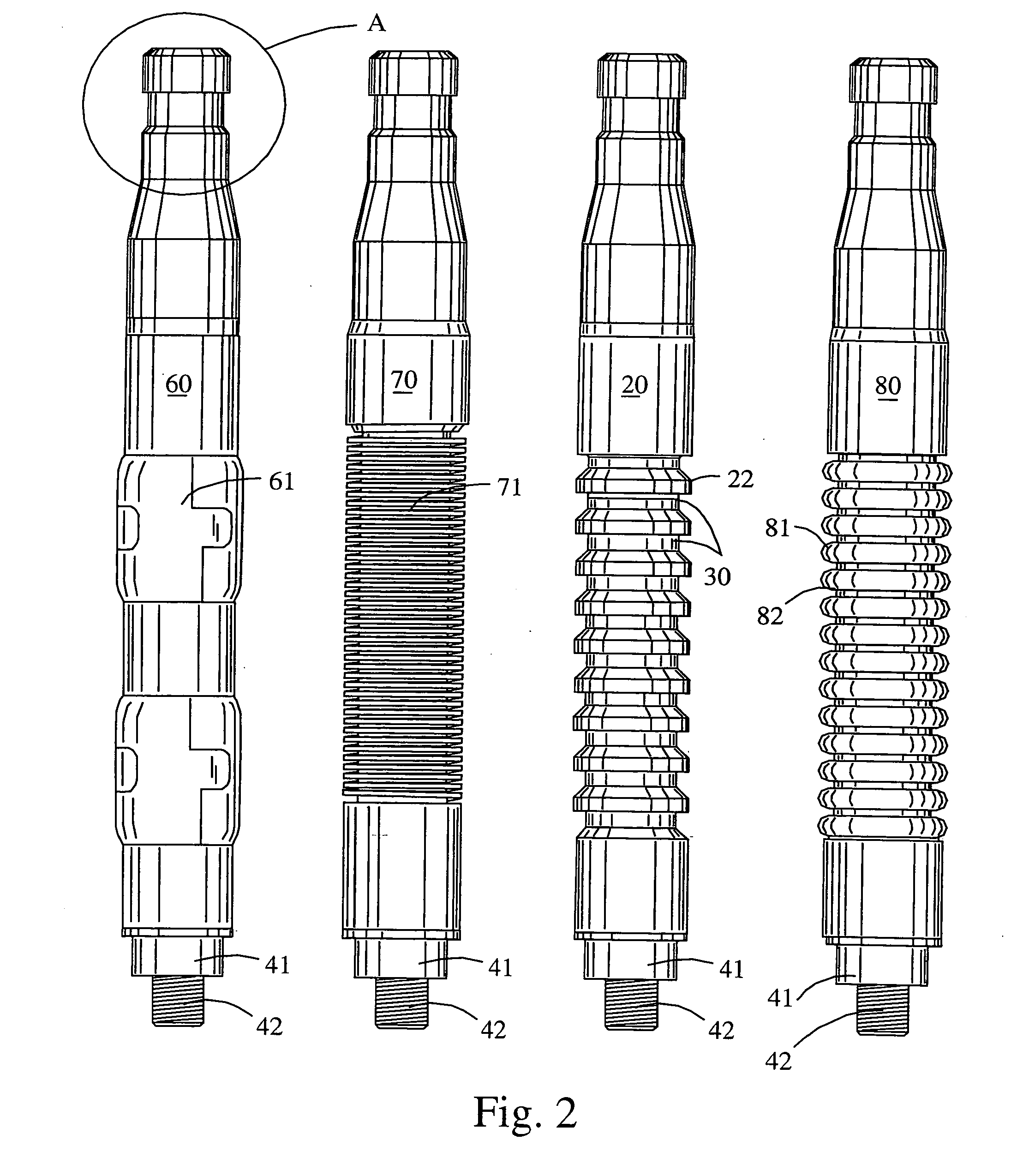
[0071]FIG. 9 is a side view of the mandrel central section of various well plungers for a dual internal shock absorber second embodiment of the present invention showing existing prior art sidewall mandrel geometries between sleeves 41. As compared to aforementioned FIG. 2, additional upper end sleeve 41 and additional upper threaded male section 42 are added for accepting an additional upper end shock absorber assembly. All geometries depicted can be found in present industrial offerings. Similar geometries also exist and will have internal orifices. FIGS. 10, 11 as described below, depict the additional shock absorbing section that is added to upper sleeve 41 via screwing onto upper threaded male section 42. Each mandrel central section is symmetrically designed to hold both an upper shock absorbing assembly 300A or 400A (FIGS. 10, 11, 12, 13) and a lower shock absorbing assembly 300 or 400 (FIGS. 4, 5, 6, 7).
[0072]FIG. 10 is a side cross-sectional view the preferred embodiment fo...
third embodiment
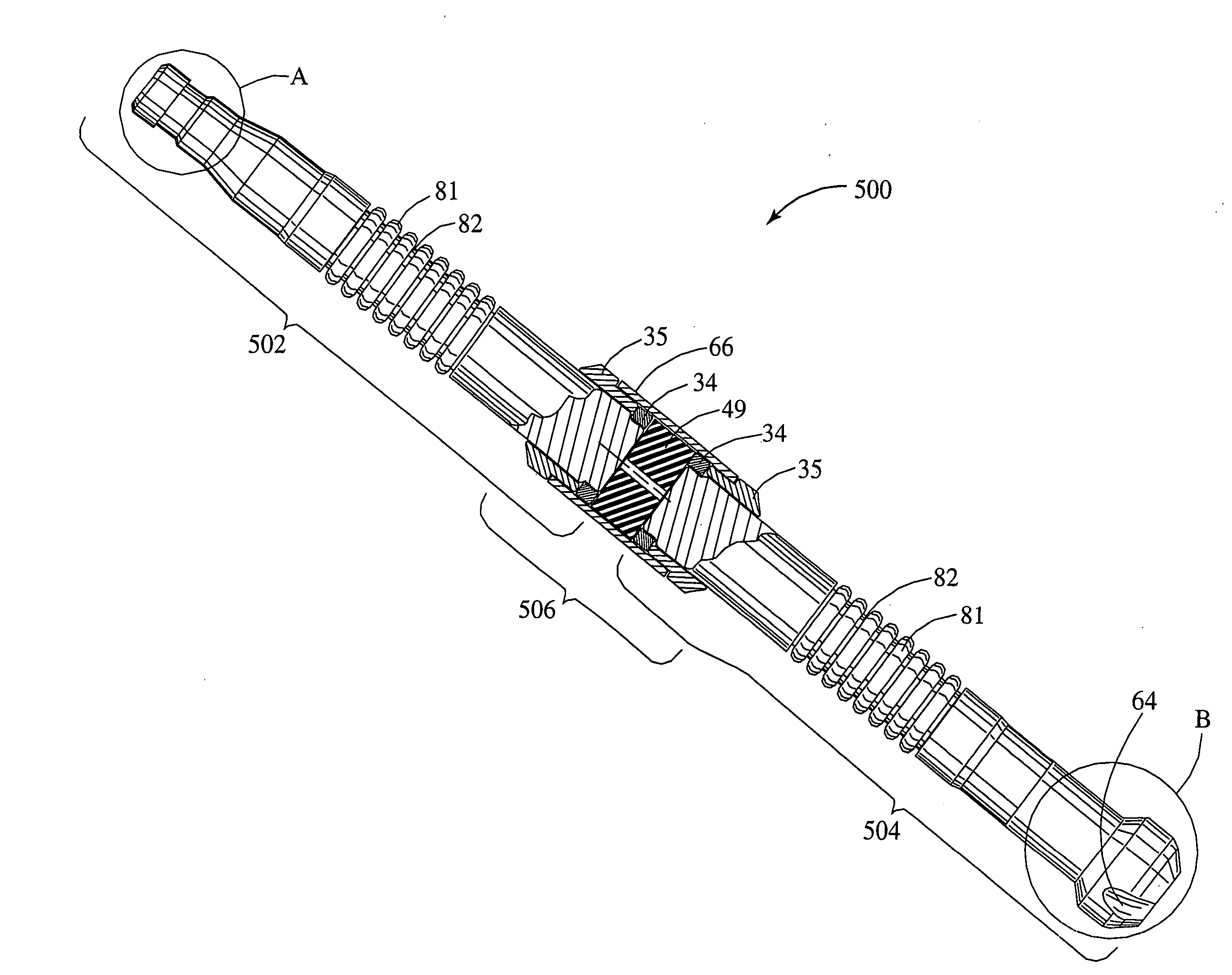
[0076]FIG. 14 is side view, including a mid-section cross-sectional view, for a mid-section internal shock absorber plunger 500 third embodiment of the present invention. For a rising plunger condition, upper mandrel 502 will hit the well top and for a falling plunger condition, lower mandrel 504 will hit the well bottom. In either case elastomer spring 49 will absorb some or all of the impact energy. Casing assembly 506 contains mid-section casing 66 having threaded interfaces at either ends, one internal elastomer spring 49, two captive nuts 34 for attaching upper mandrel 502 and lower mandrel 504, and two captive nuts 35 for containing both mandrels. Shock absorbing elastomer spring 49 could be replaced with shock absorbing die coil spring 48 (see FIG. 7) or with shock absorbing wave type spring 47 (see FIG. 7). Upper mandrel 502 at it upper end has a fishing neck A design, while lower mandrel 504 is an anvil B end design as previously shown in FIGS. 4, 5, 8. Mandrels are shown w...
PUM
 Abstract
Description
Claims
Application Information