Method for forming duct made of elastomer

a technology of elastomer and duct, which is applied in the direction of manufacturing tools, machines/engines, combustion air/fuel air treatment, etc., can solve the problems of inability to recycle rubber duct, inability to smoothly remove resin duct from the core die, and considerably inferior elasticity of resin du

Inactive Publication Date: 2006-06-15
TAIGAASU HORIMAA
View PDF21 Cites 23 Cited by
  • Summary
  • Abstract
  • Description
  • Claims
  • Application Information

AI Technical Summary

Benefits of technology

[0026] The method for forming a duct made of an elastomer according to the present invention, although using as a material a thermoplastic elastomer which is generally poor in elasticity compared with a vulcanized rubber, is suitable for a resin duct having a corrugated area as an undercut in a part of a longitudinal direction thereof and having a bended shape to a given direction. The method of the present invention ensures easy removal of an injection molded duct from a core die (including forcible ejection) not by removing the product from a core die at once with the use of forcible ejection but by conducting removal of the product gradually or stepwise in accordance with a shape or configuration of the product, particularly a molding position of a corrugated section formed [to be disposed] in the product, and resulting in escaping the damage of the product accompanied by removal of the product from the core die.

Problems solved by technology

However, such a rubber duct has some problems, that is, the rubber duct is heavier than a resin duct and it is impossible to recycle the rubber duct.
However, since the resin duct is considerably inferior in elasticity relative to the rubber duct, there is also a problem that the resin duct cannot be smoothly removed from the core die depending on the position or number of a designed corrugated section.
Further, forcible removal of the duct from the core die confronts a new problem damaging a product, resulting in deteriorating the quality of the product.

Method used


Image

  • Method for forming duct made of elastomer
  • Method for forming duct made of elastomer
  • Method for forming duct made of elastomer

Examples


first embodiment

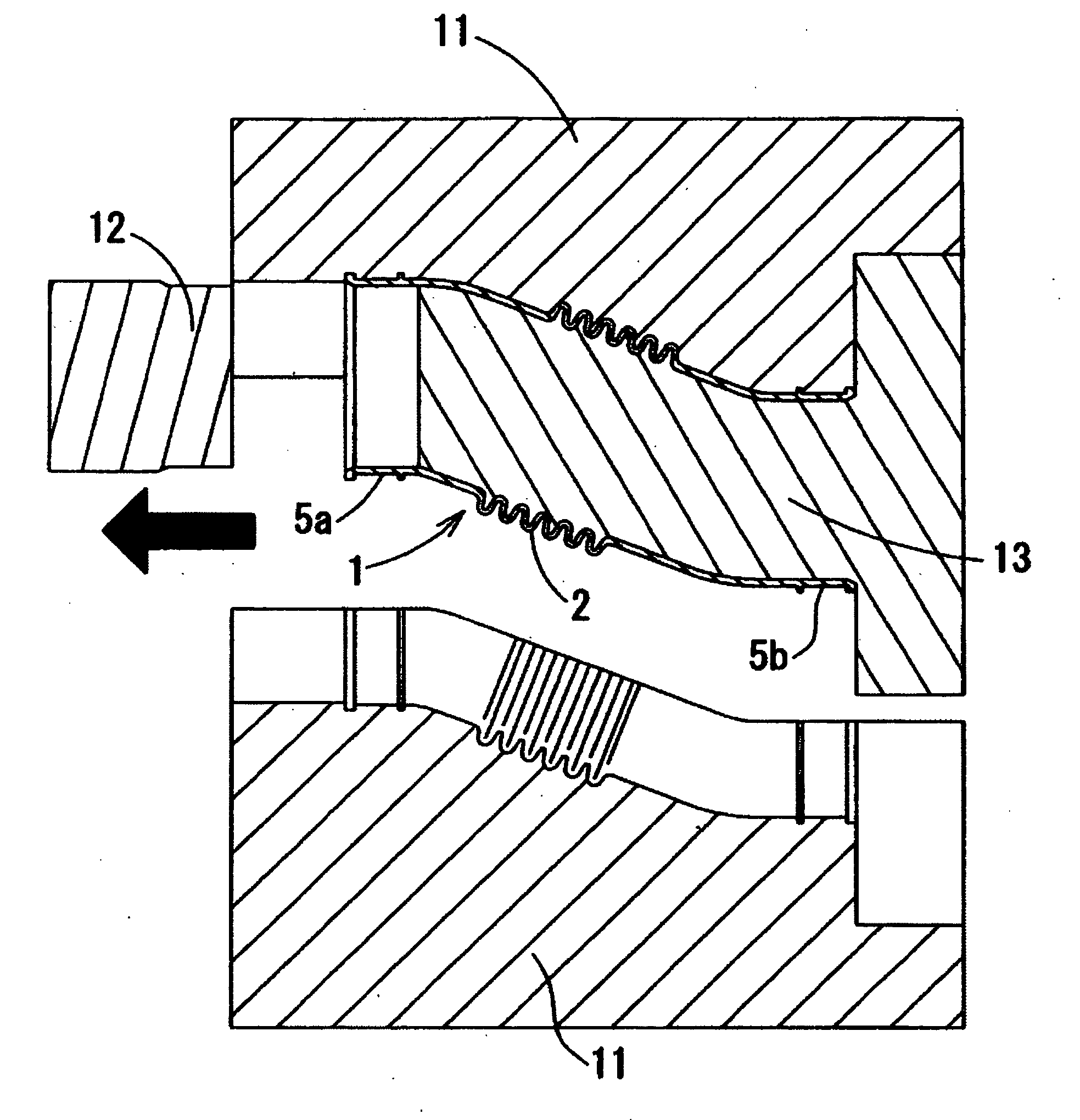
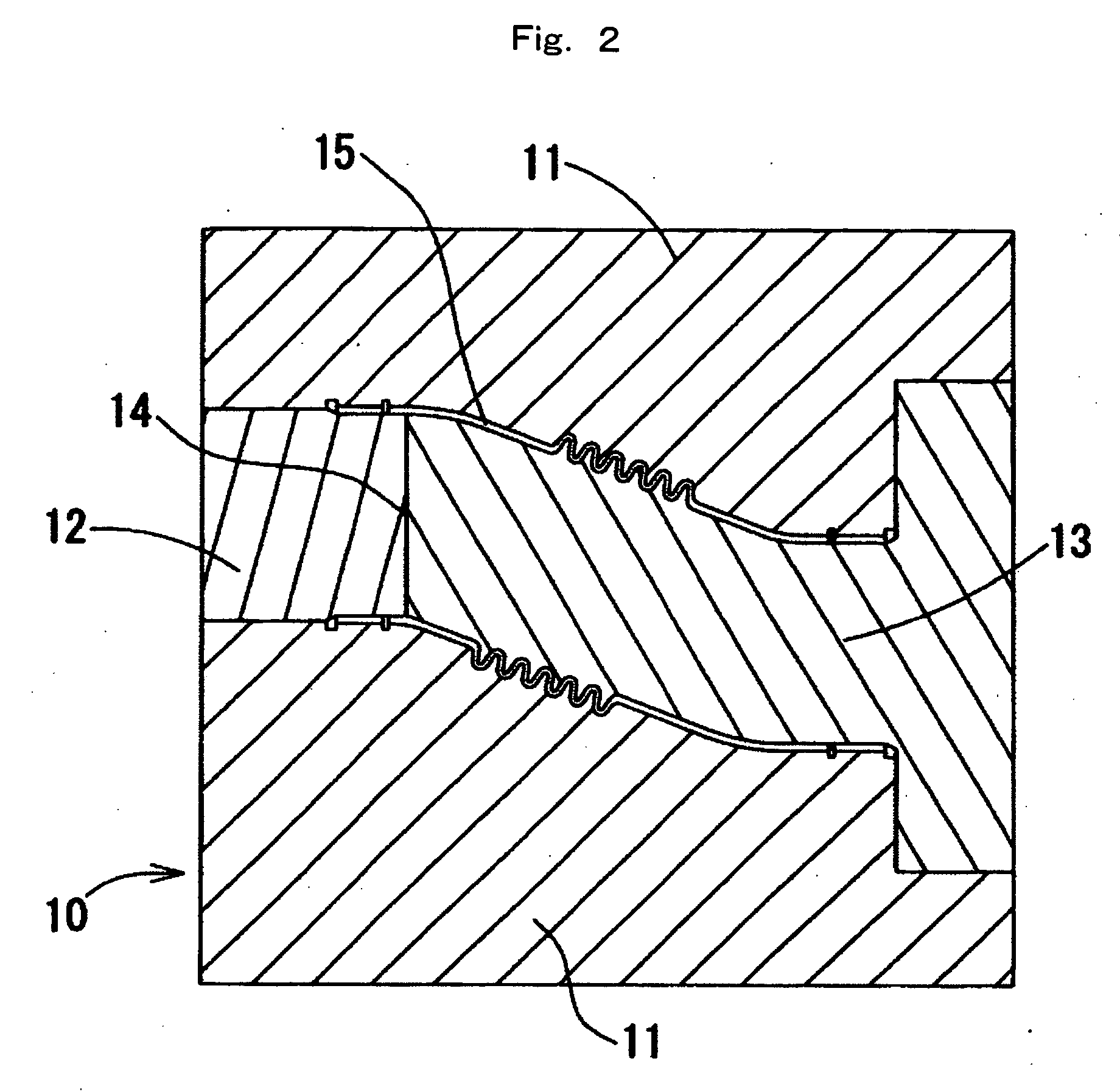
[0048]FIG. 9 shows the second die-removing step of the resin duct 21. After opening the die by further sliding the second part 31b of the other cavity die 31 in a perpendicular direction relative to the longitudinal direction, an cylindrical ejection jig 37 having an almost short-cylindrical configuration is inserted into (or attached to) the inside of a part of one end of the resin duct 21 from which the first core die 32 has been already pulled out. As it is, the remainder area 23 of the resin duct 21 is pulled out from the second core die 33. On the occasion or operation, preferably in the same manner as the above-mentioned first embodiment, air is blown out from the air inlet 38 of the ejection jig 37 to the inside so as to enter between the second core die 33 and the remainder area 23 of the resin duct 21, thereby the die can be removed while expanding the remainder area 23 in the radius direction. Then, as shown in FIG. 10, the resin duct 21 is pulled out together with the eje...

second embodiment

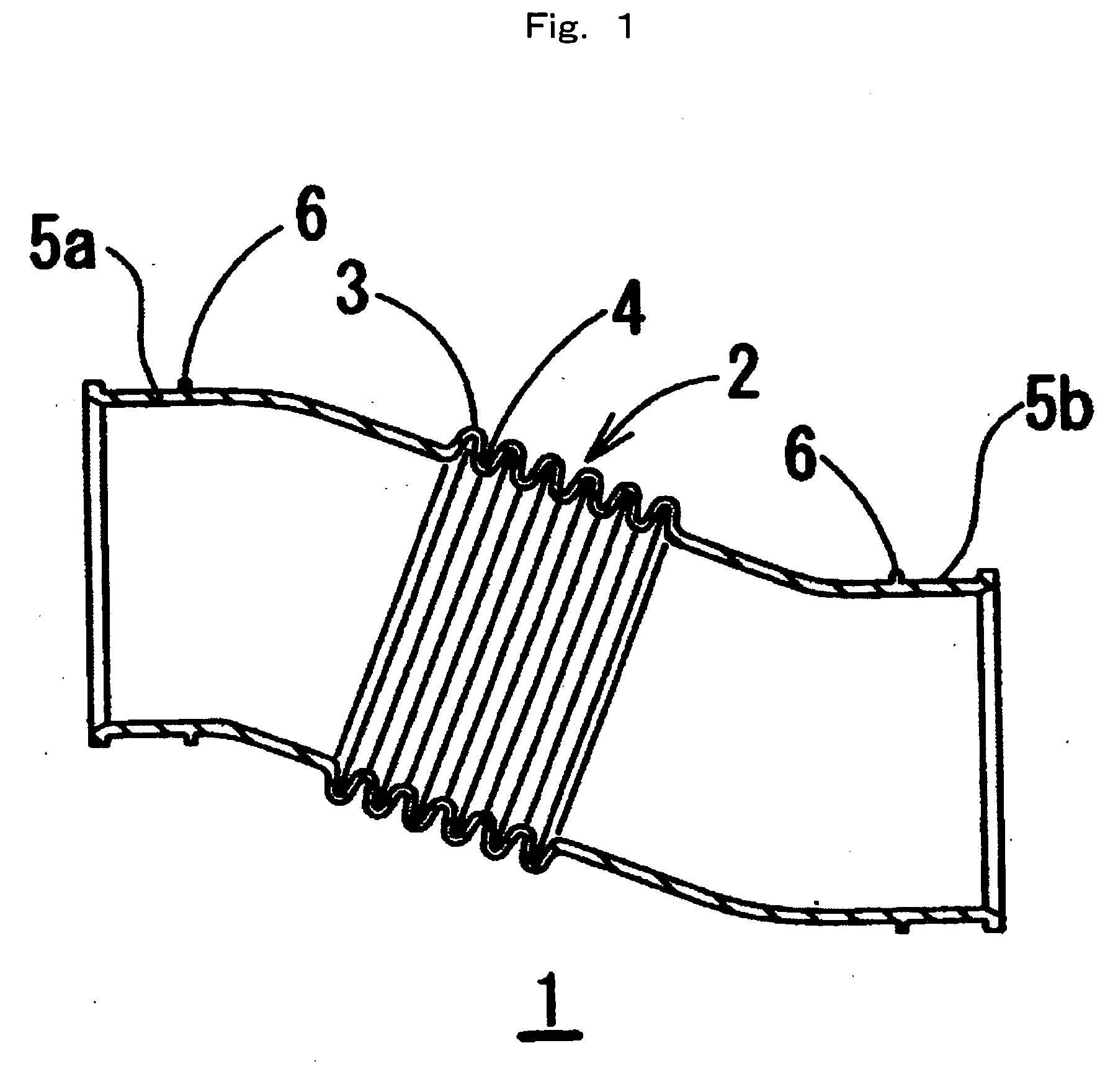
[0049] Incidentally, as shown in FIG. 11, a duct 41 having corrugated sections which forms a plurality of undercuts, a first corrugated section 42 and a second corrugated section 43, along the longitudinal direction, can be also formed by applying the present That is, the corrugated section 22 of the above-mentioned resin duct 21 corresponds to a duct area (or part or segment) containing the first corrugated section 42, and the remainder area 23 of the duct corresponds to a duct area containing the second corrugated section 43. In the first die-removing step, one of splittable core dies (not shown) is pulled out from a first die-removing area 44 containing the first corrugated section 42 for removing the die, and in the second die-removing step, a second die-removing area 45 containing the second corrugated section 43 is pulled out from the other divided core die (not shown) for removing the die.

[0050] The die unit of the present invention, for forming an elastomer duct having a co...


PUM

PropertyMeasurementUnit
areaaaaaaaaaaa
thermoplasticaaaaaaaaaa
elasticityaaaaaaaaaa

Abstract

[Objects] In a method for forming a duct used as, e.g., an air duct for an automobile engine, and provided with a corrugated section as an undercut part in a part of the longitudinal direction of the duct, an elastomeric duct is formed with ensuring easy removal of a duct molded by injection from a core die even when the duct is made of a resin poor in elasticity. [Means to Solve the Problems] A method for forming an elastomeric duct having a corrugated section in a longitudinal direction thereof as a part of the duct by injection molding, which comprises injecting an elastomer material into a cavity formed with a cavity die for forming an external surface of the duct, and a core die for forming an internal surface of the duct, wherein the core die is a splittable core die which is axially splittable into two parts, one is a core die A for forming a duct area at least containing the corrugated section, and the other is a core die B for forming a duct area free from the corrugated section, and removing the duct area containing the corrugated section from the core die A with expanding at least the corrugated section in the radius direction by air injection after opening the cavity die.

Description

TECHNICAL FIELD [0001] The present invention relates to a method for forming or producing an elastomeric duct or a duct made of an elastomer such as a rubber or a thermoplastic elastomer, for example, a duct as an air duct (such as an air intake duct for an automobile engine) for supplying air from an air cleaner to an engine. In particular, the present invention relates to a duct comprising a corrugated section as an undercut part at a part of a longitudinal direction thereof. BACKGROUND ART [0002] Heretofore, as the above-mentioned duct, a rubber duct has been used which is an injection-molded article from a vulcanized rubber material. However, such a rubber duct has some problems, that is, the rubber duct is heavier than a resin duct and it is impossible to recycle the rubber duct. In recent years, in order to solve these problems, an air duct which is an injection molded article formed from a thermoplastic elastomer, particularly a polyolefinic thermoplastic elastomer, is in pra...

Claims


Application Information

Patent Timeline
Patent Type & Authority Applications(United States)
IPC IPC(8): B29C45/00B29C45/43F02M35/10
CPCB29C45/435B29K2021/00B29L2016/00F02M35/10137F02M35/10321F02M35/10347
Inventor TAKADA, SEIICHIROOMORI, NAOKI
Owner TAIGAASU HORIMAA
Why Eureka
Try Eureka