Image signal display apparatus

a liquid crystal display and image signal technology, applied in the direction of instruments, static indicating devices, etc., can solve the problems of inability to accurately measure the time at which the corrected result is output, and the time at which the corrected result is not well synchronized, so as to increase the number of effective display gradations, reduce backlight power consumption, and increase contrast

Inactive Publication Date: 2006-06-15
HITACHI LTD
View PDF4 Cites 76 Cited by
  • Summary
  • Abstract
  • Description
  • Claims
  • Application Information

AI Technical Summary

Benefits of technology

[0016] According to the present invention, the device characteristics of both liquid crystal panel and the backlight are obtained as signals, a screen to be displayed is generated as the driving signals of the liquid crystal panel and the backlight, both signals are serially transmitted to the driving circuits of the liquid crystal panel and the backlight, and the liquid crystal panel and the backlight are synchronized for displaying an image for each frame. This gives a display output, generated by combining the device characteristics of the liquid crystal panel and the backlight, increases the number of effective display gradations, increases the contrast, and reduces the backlight power consumption.

Problems solved by technology

One of the problems with the technology disclosed in Japanese Patent No. 3430998 is that the time at which the signals are measured in a screen, the time at which the signals are corrected based on the measured result, and the time at which the corrected result is output are not well synchronized.
Because a moving image signal in the screen varies from frame to frame, the dynamic range correction according to the prior art disclosed in Japanese Patent No. 3430998 is inconsistent in principle.

Method used


Image

  • Image signal display apparatus
  • Image signal display apparatus
  • Image signal display apparatus

Examples


second embodiment

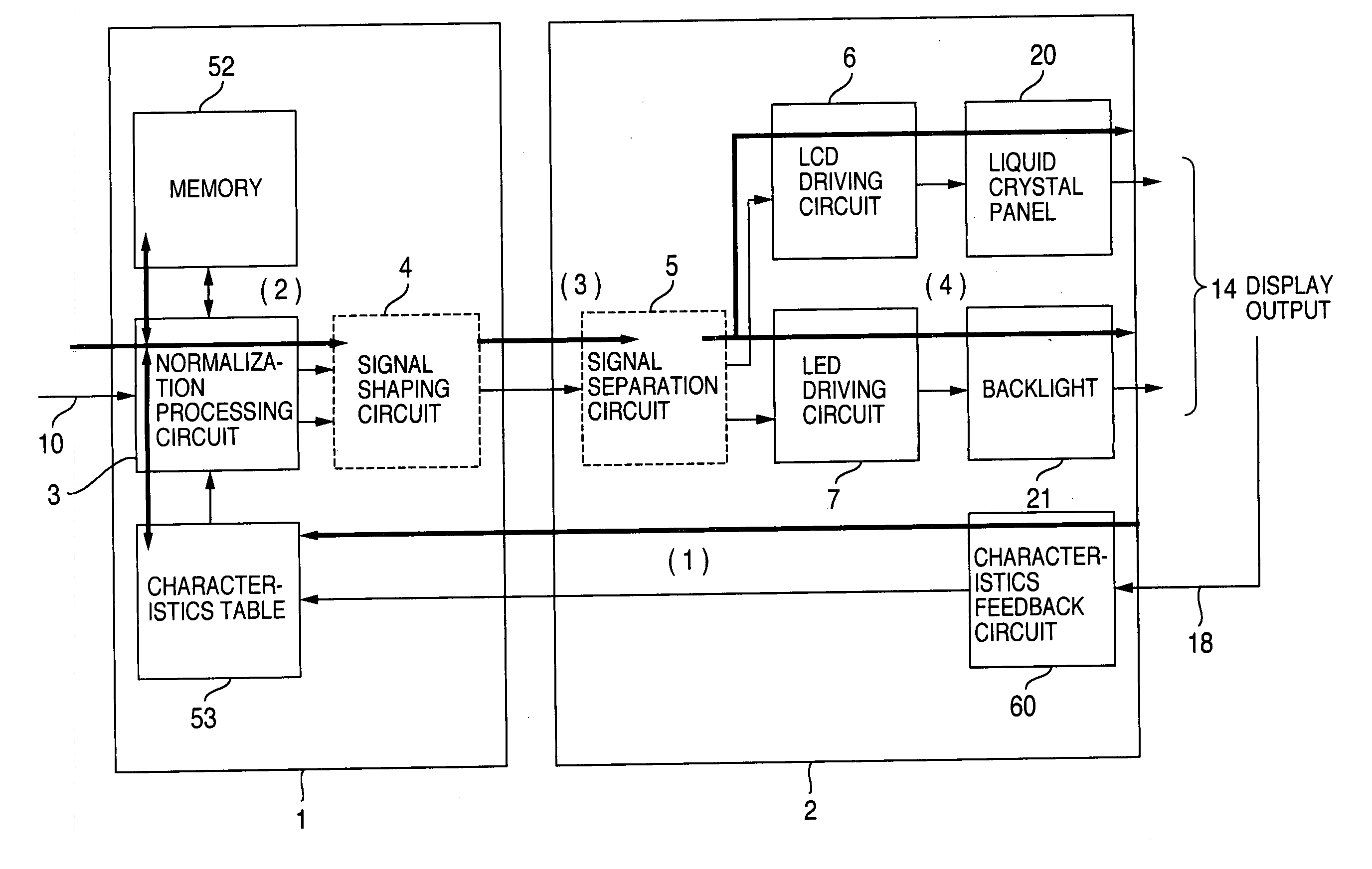
[0085]FIG. 5 is a diagram showing a control unit 1 and a display 2 constituting an apparatus according to the present invention. In the description below, the major signal flows indicated by bold lines are classified into four as shown by the arrows in the figure.

(1) Setting of Display Characteristics

[0086] The characteristics of the display 2 are collected as a sensor signal 18 and are transmitted to the control unit 1 via a characteristics feedback circuit 60.

[0087] The sensor signal 18 may be either a variable component collected by a sensor or static characteristics of the display 2. The sensor signal 18 is collected, and the characteristics are transmitted from the characteristics feedback circuit 60 to the control unit 1, any time, for example, when the apparatus is shipped from the factory, when the power is turned on, when the calibration operation is performed, or at a predetermined interval of time. The collected and transmitted characteristics data, stored in a charac...

third embodiment

(1) Backlight, Display Panel, and Normalization

[0092] The following describes light emission unit constituting the backlight of a display, with emphasis on the configuration of an apparatus that emits light in a plane using solid light emitting elements such as LEDs.

[0093]FIG. 6 is a diagram showing the cross section of the configuration in which three light emission unit are arranged. For simplicity, assume that the light emission unit are arranged with no space between them and that light emission unit each emit the same amount of light in the corresponding in-plane area. Then, supplying the driving signal individually to each light emission unit produces a light emission distribution according to the step function. Because the area of light emission distribution by each light emission unit is in general larger than one pixel area of the liquid crystal panel, one light emission unit of the backlight illuminates multiple pixels of the liquid crystal panel at the same time. This ...

fourth embodiment

[0119] The present invention is characterized in that an image signal is transmitted and displayed using two types of signals (normalized signal and normalization coefficient) in normalization representation and in that a new method and means are defined for transmitting an image signal in a new representation format. In particular, because it is important for the transmission of an image signal to be compatible with existing apparatuses, the present invention also proposes a method for smoothly moving from the conventional image transmission method to the image transmission method according to the present invention.

(1) Circuit Configuration

[0120]FIG. 10 is a diagram showing an example of the circuit configuration for implementing the present invention. FIG. 10A shows the configuration in which the signal is transmitted serially from a control unit to a display, and FIG. 10B shows the configuration in which the signal is transmitted in parallel from a control unit to a display. F...


PUM


Abstract

A liquid crystal display apparatus includes a liquid crystal display panel having a liquid crystal layer held between a pair of substrates; and a light source, a whose brightness of which is controllable, wherein the liquid crystal display apparatus further includes a unit for generating an image signal with a signal for controlling the liquid crystal layer configured in a display area of a frame-based pixel configuration and with a signal for controlling the light source configured in a blanking interval of the frame-based pixel configuration.

Description

BACKGROUND OF THE INVENTION [0001] The present invention relates to the transmission method of the driving signal of a liquid crystal display apparatus. [0002] Recently, a technology has been developed for use on a display apparatus, configured by a liquid crystal panel and a backlight, where LEDs (Light-Emitting Diode) are used on the backlight. An LED that reflects or guides light can be used as a surface light emitter of any shape and, due to its steep emission spectrum, can reproduce high-saturation colors. Another advantage is a high-speed driving control ability that allows the backlight brightness to be adjusted with the display on the liquid crystal panel. [0003] A technology for controlling both video signals and the light source brightness is disclosed in Japanese Patent No. 3430998. For use on a liquid crystal display, this patent discloses an apparatus configuration and a method in which, with signal amplitude control unit and light source control unit, the video signals...

Claims


Application Information

Patent Timeline
Patent Type & Authority Applications(United States)
IPC IPC(8): G09G3/36
CPCG09G3/2096G09G3/342G09G3/3426G09G2320/0261G09G2320/0646G09G2360/16G09G3/36G09G3/20
Inventor INUZUKA, TATSUKIYAMAMOTO, TSUNENORIKONNO, AKITOYOHIYAMA, IKUO
Owner HITACHI LTD
Why Eureka
Try Eureka