Systems and methods for de-blurring motion blurred images

a motion blurred image and motion blur technology, applied in the field of systems and methods for deblurring motion blurred images, can solve problems such as blurred images, camera shake, and common motion blur due to camera shak

Inactive Publication Date: 2006-06-15
THE TRUSTEES OF COLUMBIA UNIV IN THE CITY OF NEW YORK
View PDF10 Cites 98 Cited by
  • Summary
  • Abstract
  • Description
  • Claims
  • Application Information

AI Technical Summary

Benefits of technology

[0016] An object of the present invention is to provide a technique for correcting blurring introduced into an image due to camera motion.
[0017] A further object of the present invention is to provide a technique for correcting blurring introduced into an image due to camera motion by using associated motion information.
[0018] Another object of the present invention is to provide an apparatus able to capture all information required to correct blurring introduced into an image due to camera motion.
[0019] Still another object of the present invention is to provide an apparatus for capturing a motion blurred image, de-blurring the image, and providing a user with a de-blurred image.
[0023] In still another preferred arrangement, the primary detector is a first portion of a dual-resolution sensor and the secondary detector a second portion of the dual-resolution sensor. The ratio of the first predetermined resolution to said second predetermined resolution is preferably 9:1 in terms of the scene energy incident on the sensor. The two portions may advantageously be formed on a single chip, to ensure a low cost and compact system.

Problems solved by technology

Motion blur due to camera shake is a common problem in photography, especially in conditions involving zoom and low light.
Merely pressing a shutter release button on the camera can in and of itself cause the camera to shake, and unfortunately cause blurred images.
This problem is especially prevalent in digital photography, where lightweight cameras with automated exposure times are not easily stabilized are common, and where automated exposure times often necessitate relatively long stabilization to ensure a non blurred image.
The compact form and small lenses of many of these cameras only serves to increase this problem.
If during this time—the exposure time—the image moves, either due to camera or object motion, the resulting image will exhibit motion blur.
The problem of motion blur is increased when a long focal length (zoom) is employed, since a small angular change of the camera creates a large displacement of the image, and in situations when long exposure is needed, either due to lighting conditions, or due to the use of small aperture.
One limitation is that only professionals are likely to use a tripod and shutter release cable on a regular basis.
Moreover, the use of a tripod does not solve the problem of shooting from a moving platform, such as car, train, helicopter or balloon.
However, objects in bright daylight may still have motion blur and, of course, flash photography is useful only if the distance between the flash and the object is small.
However, it cannot eliminate blur completely.
Moreover, Sensitive sensors (both film and CCD) produce noisy and grainy images.
Unfortunately, cost and weight also significantly increase with an increased lens aperture, and a tripod may be required to comfortably handle such weight.
While this technology is used in stabilized zoom lens for Single Lens Reflex (“SLR”) cameras, it is costly, and its effectiveness is limited to approximately 1 / 60 of a second for typical 400 mm zoom lens.
The sensitivity of such system to very slow motion may also be limited, and may suffer from drift.
In addition, such system cannot compensate for constant speed motion, such as occurs when taking images from a moving train.
Accordingly, while addressing the problem of motion of the camera itself is useful in certain applications, it does not provide an adequate solution to the problem of motion blur as such systems are either limited, very costly, or both.
However, while approaches which either assume that the point spread function is known or can be modeled by a simple function and found automatically from the image itself, no satisfactory solutions have thus far been provided.
In particular, it has been difficult to obtain a useful point spread function useful in a de-blurring algorithm since inaccurate point spread functions tends to create strong artifacts, making them unpleasant for the eye.

Method used


Image

  • Systems and methods for de-blurring motion blurred images
  • Systems and methods for de-blurring motion blurred images
  • Systems and methods for de-blurring motion blurred images

Examples


Embodiment Construction

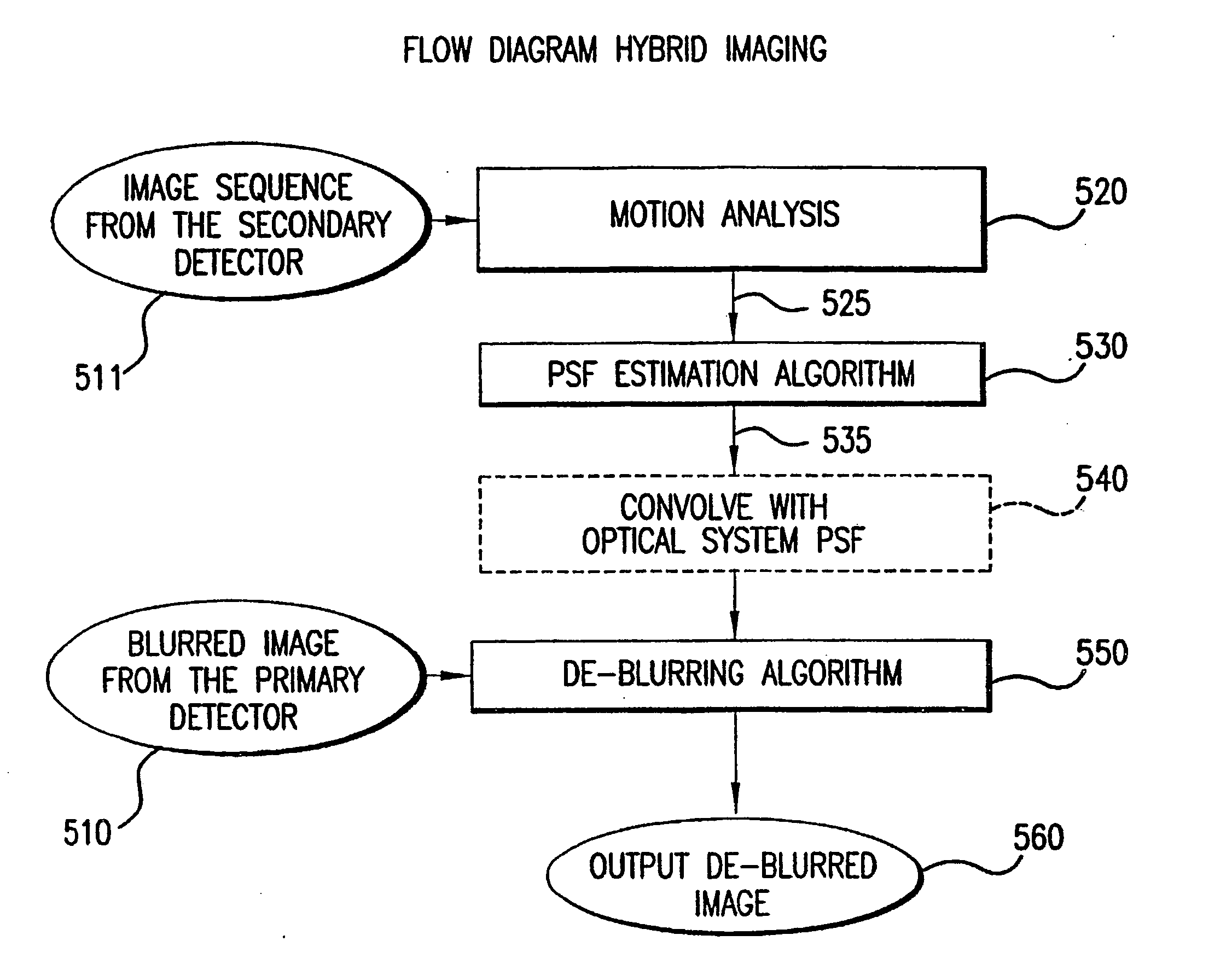
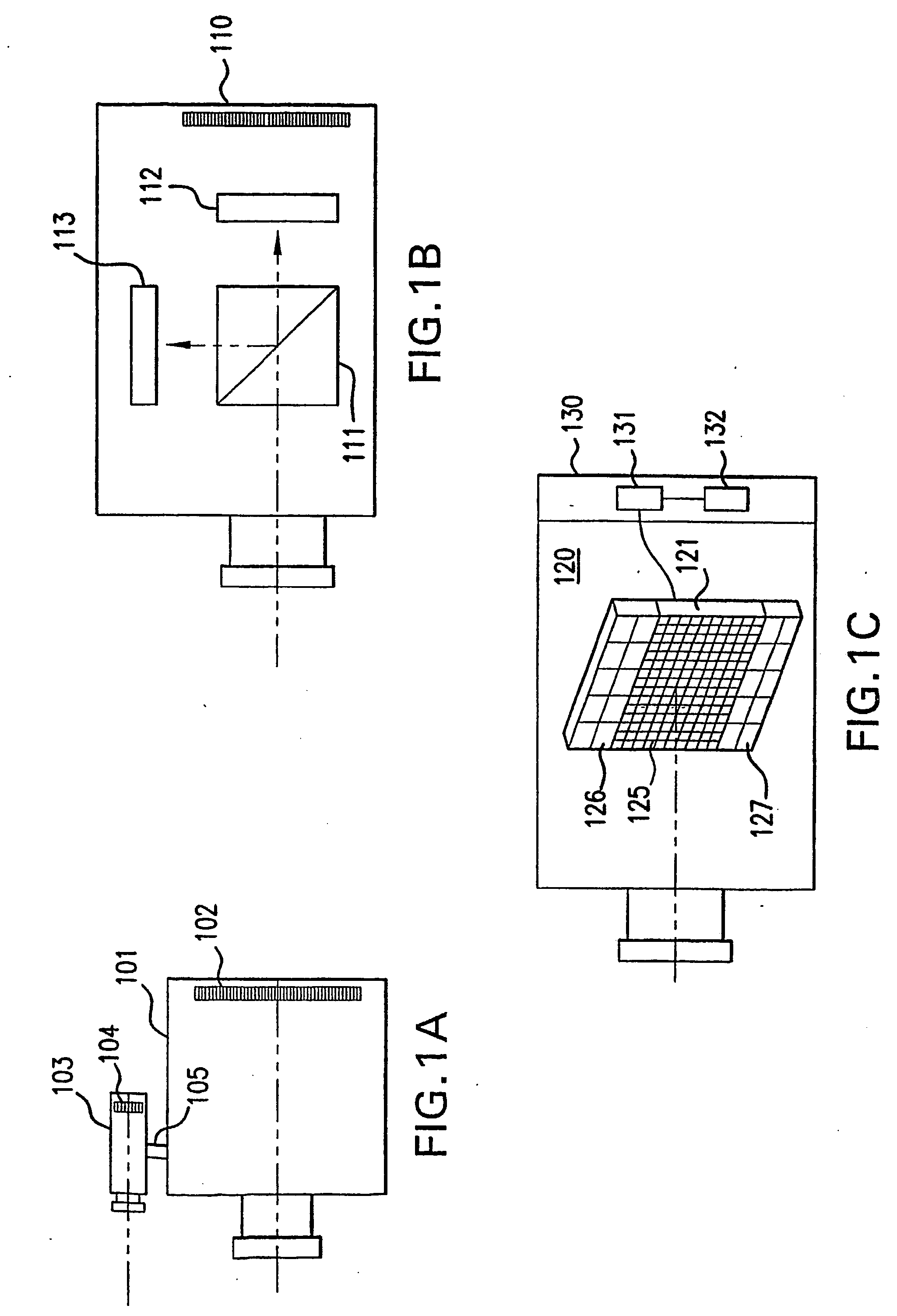
[0038] Referring to FIGS. 1(a)-(c), exemplary hybrid camera systems in accordance with the present invention are shown. Each system includes a primary image detector for capturing an image of the scene, as well as a secondary detectors for capturing information useful for correcting blurring introduced into the image due to camera motion.

[0039] The embodiment shown in FIG. 1(a) uses two cameras 101, 103 connected by a rigid member 105. Camera 101 is preferably a high-resolution still camera, and includes the primary detector 102 to capture an image of a scene. Camera 103 is preferably a low-resolution video camera which includes a secondary detector 104.

[0040] The secondary detector 104 is used for obtaining motion information, and therefore must capture a minimum of two frames of digital video information in order to provide such motion information. Preferably, fifteen or more frames are captured during the integration time of camera 101. While the embodiment shown with reference...


PUM


Abstract

Systems and methods for providing a substantially de-blurred image of a scene from a motion blurred image of the scene are disclosed. An exemplary system includes a primary detector for sensing the motion blurred image and generating primary image information representing the blurred image, a secondary detector for sensing two or more secondary images of the scene and for generating secondary image information representing the two or more secondary images, and a processor for determining motion information from the secondary image information, estimating a point spread function for the motion blurred image from the motion information, and applying the estimated point spread function to the primary image information to generate information representing the substantially de-blurred image.

Description

CROSS-REFERENCE TO RELATED APPLICATIONS [0001] This application is based on U.S. provisional patent application Ser. No. 60 / 390,336, filed Jun. 21, 2002, which is incorporated herein by reference for all purposes and from which priority is claimed.NOTICE OF GOVERNMENT RIGHTS [0002] The United States government has certain rights in the present invention pursuant to National Science Foundation ITR Award IIS-00-85864.BACKGROUND OF THE INVENTION [0003] 1. Technical Field [0004] The present invention relates to techniques for digitally capturing and processing still images of a scene using an image detector, and more particularly, to techniques for correcting blurring introduced into such images due to motion of the image detector. [0005] 2. Background Art [0006] Motion blur due to camera shake is a common problem in photography, especially in conditions involving zoom and low light. Merely pressing a shutter release button on the camera can in and of itself cause the camera to shake, a...

Claims


Application Information

Patent Timeline
Patent Type & Authority Applications(United States)
IPC IPC(8): H04N5/217H04N5/228H04N5/232
CPCG06T5/50G06T7/20H04N5/23248H04N5/23254H04N5/23258H04N5/23264H04N5/23277H04N5/2628G06T5/003G06T2207/20201H04N23/6845H04N23/682H04N23/6811H04N23/68H04N23/6812
Inventor BEN-EZRA, MOSHENAYAR, SHREE K.
Owner THE TRUSTEES OF COLUMBIA UNIV IN THE CITY OF NEW YORK
Why Eureka
Try Eureka