Wireless base station device and rate control method thereof

a wireless base station and wireless base station controller technology, applied in data switching networks, instruments, frequency-division multiplexes, etc., can solve the problem of increasing the bandwidth cost of the wired line between the wireless base station and the wireless base station controller to meet the increased throughput of the wireless line, and achieve the effect of reducing the bandwidth cost of the wired line and efficiently controlling the wired lin

Inactive Publication Date: 2006-06-15
NEC CORP
View PDF8 Cites 51 Cited by
  • Summary
  • Abstract
  • Description
  • Claims
  • Application Information

AI Technical Summary

Benefits of technology

[0010] It is an object of the present invention, when high peak-throughput, high burstiness data is processed by a data communication method such as HSDPA, to increase the utilization of a wired line and to minimize the wired line cost that is increased by the introduction of HSDPA.
[0015] According to the present invention, a wireless base station device controls the data flow amount of each user considering the data holding amount in a higher-level station device (wireless base station controller) when congestion is detected. This allows the bandwidth of a wired line to be efficiently controlled between the wireless base station and the wireless base station controller while minimizing the occurrence of a buffer overflow in the wireless base station controller when congestion occurs. Therefore, the bandwidth cost of the wired line can be reduced.

Problems solved by technology

That is, in an HSDPA wireless base station device where the same spread encoder is time-shared by multiple users to increase the utilization of a wireless resource for higher throughput of user data, one of the problems is that the bandwidth cost of the wired line between a wireless base station and a wireless base station controller is increased to meet the increased throughput of the wireless line.

Method used


Image

  • Wireless base station device and rate control method thereof
  • Wireless base station device and rate control method thereof
  • Wireless base station device and rate control method thereof

Examples


first embodiment

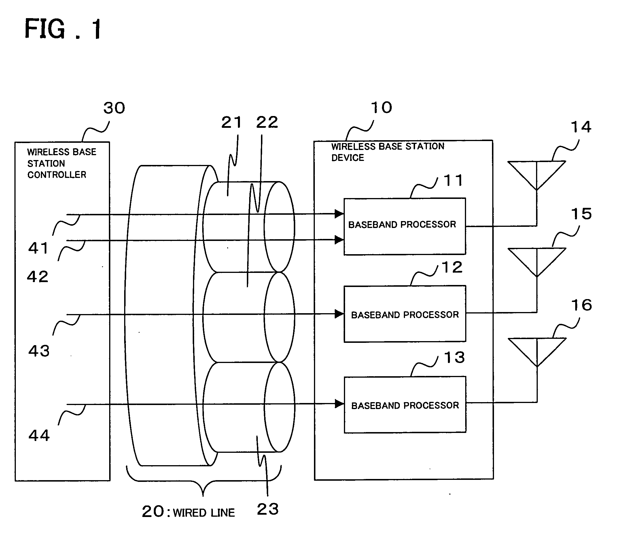
[0022]FIG. 1 is a block diagram showing the configuration of the connection between a wireless base station device in a first embodiment of the present invention and a wireless base station controller. Referring to FIG. 1, a wireless base station device 10 comprises baseband processors 11, 12, and 13 each of which has an antenna 14, 15, or 16, respectively. The wireless base station device 10 is connected to a wireless base station controller 30 via a wired line 20. In the description below, the wireless base station device 10 covers three cells (cells #1, #2, and #3) and has baseband processors 11, 12, and 13, one for each cell. Note that the number of cells is not limited to three.

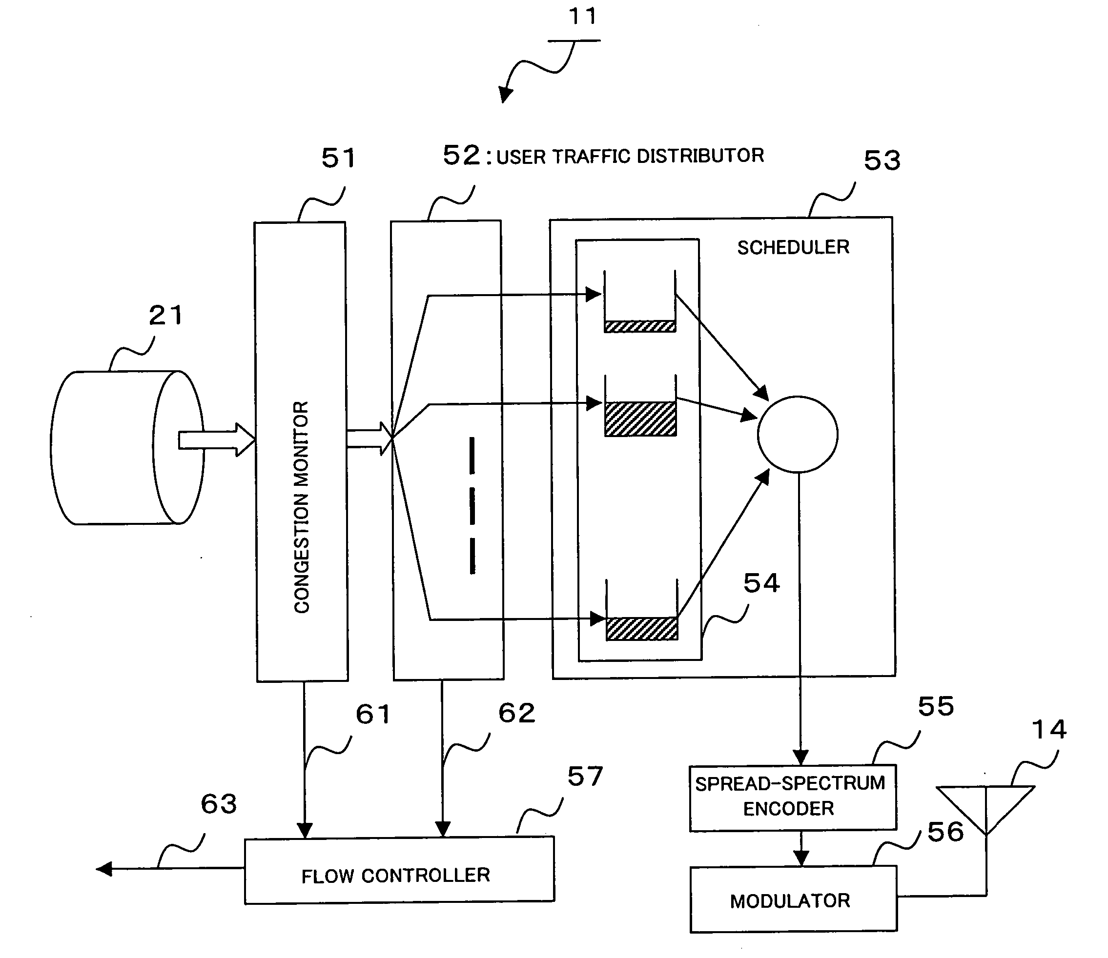
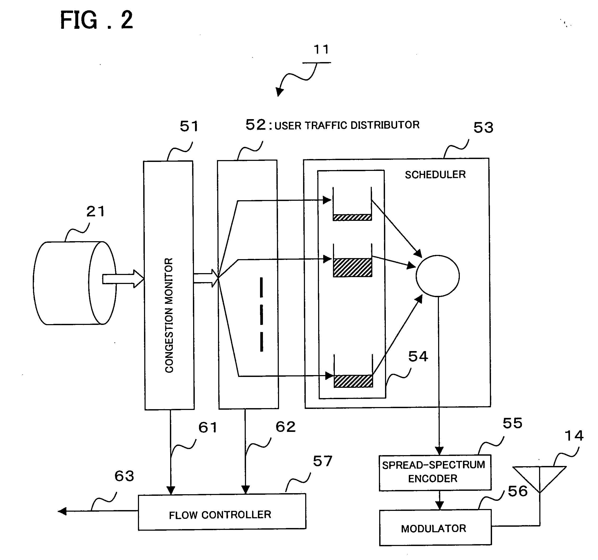
[0023] Each of the baseband processors 11, 12, and 13 once stores a user traffic from the wireless base station controller 30 into the buffer, performs spread spectrum modulation according to the data traffic priority among the users in the same cell, and sends the modulated data to wireless lines via t...

second embodiment

[0045]FIG. 4 is a flowchart showing the operation of baseband processor in a second embodiment of the present invention. In FIG. 4, in a step with the same reference numeral as that in FIG. 3, the same operation is performed and therefore the description of that step will be omitted. The processing in FIG. 4 differs from the processing in FIG. 3 in that the traffic amount at congestion occurrence time is controlled considering user's priority. For example, in step S15a, the maximum holding time TMAX—flow—Priority(kj), which is the maximum holding time with priority considered, is used instead of the maximum holding time TMAX—flow.

[0046] The maximum holding time TMAX—flow—Priority(kj) with priority considered is generated by correcting the maximum holding time TMAX—flow as shown in expression (4).

TMAX—flow—Priority(kj)=α(P)*TMAX—flow  Expression (4)

α(P), which is a coefficient determined according to the priority of each user, is the coefficient for a user with priority P. At this...


PUM


Abstract

A wireless base station device, connected to a higher-level station device via a wired line, comprises baseband processors 11, one for each virtual link 21 to which user data flows belong. In the baseband processor 11, a congestion monitor 51 monitors the reception bandwidth usage rate of a virtual link allocated to each cell for detecting congestion and, upon detecting congestion, sends a notification to a flow controller 57. A user traffic distributor 52 distributes a received user traffic into the traffic flow of each user and, at the same time, extracts, for each user data flow, the buffer holding amount in the higher-level station device where user data flows are multiplexed and sends a notification to the flow controller 57. The flow controller 57 manages the data flow of each user and, in response to a congestion notification from the congestion monitor 51, requests the higher-level station device to reduce the rate of a user data flow in descending order of rates beginning with a data flow with a highest rate.

Description

FIELD OF THE INVENTION [0001] The present invention relates to a wireless base station device and its rate control method, and more particularly to a wireless base station device that processes high peak-throughput, high-burstiness data and to a data flow rate control method used in the wireless base station device. BACKGROUND OF THE INVENTION [0002] Recently, the size of contents available for a mobile phone becomes larger and larger. In future, there will be a rapidly increasing need for the high-speed transmission of large contents such as those used in moving-picture delivery. To meet the need for such a high-speed data communication, there is a best effort packet data communication method called High Speed Downlink Packet Access (HSDPA). This method employs the adaptive modulation / coding scheme and the packet combination hybrid ARQ (Automatic Repeat Request) to increase the speed, and improve the quality, of data communication. [0003] Such a best effort packet data communicatio...

Claims


Application Information

Patent Timeline
Patent Type & Authority Applications(United States)
IPC IPC(8): H04L12/26H04Q7/00H04J3/22H04Q7/24H04L1/00H04J3/16H04J13/00H04L29/08H04W24/00H04W28/00H04W28/08H04W28/10H04W28/14H04W28/22H04W88/08H04W92/00
CPCH04L47/10H04L47/11H04L47/14H04L47/2441H04L47/263H04L47/30H04L47/33H04W24/00H04W28/08H04W28/14H04W28/22H04W88/08H04W28/0231H04W28/0252H04W28/10H04W8/04
Inventor NAKAYASU, KANADA
Owner NEC CORP
Why Eureka
Try Eureka