Acoustic correction apparatus

a correction apparatus and acoustic technology, applied in the field of audio enhancement systems, can solve the problems of distorted sound pressure response over the audible frequency spectrum, degrade the quality of reproduced sound as perceived by the listener, and the inability to reproduce reverberant sounds, etc., to achieve the effect of enhancing the quality of audio sound

Inactive Publication Date: 2006-06-15
DTS
View PDF99 Cites 105 Cited by
  • Summary
  • Abstract
  • Description
  • Claims
  • Application Information

AI Technical Summary

Benefits of technology

[0022] The present invention solves these and other problems by providing a signal processing technique that significantly improves the image size, bass performance and dynamics of an audio system, surrounding the listener with an engaging and powerful representation of the audio performance. It improves the listening experience for a variety of applications, including computer, multimedia, televisions, boom-boxes, automobiles, home audio, and portable audio systems. In one embodiment, the sound correction system corrects for the apparent placement of the loudspeakers, the image created by the loudspeakers, and the low frequency response produced by the loudspeakers. In one embodiment, the sound correction system enhances spatial and frequency response characteristics of sound reproduced by two or more loudspeakers. The audio correction system includes an image correction module that corrects the listener-perceived vertical image of the sound reproduced by the loudspeakers, a bass enhancement module that improves the listener-perceived bass response of the loudspeakers, and an image enhancement module that enhances the listener-perceived horizontal image of the apparent sound stage.
[0023] In one embodiment, three processing techniques are used. Spatial cues responsible for positioning sound outside the boundaries of the speaker are equalized using Head Related Transfer Functions (HRTFs). These HRTF correction curves account for how the brain perceives the location of sounds to the sides of a listener even when played back through speakers in front of the listener. As a result, the presentation of instruments and vocalists occur in their proper place, with the addition of indirect and reflected sounds all about the room. A second set of HRTF correction curves expands and elevates the apparent size of the stereo image, such that the sound stage takes on a scale of immense proportion compared to the speaker locations. Finally, bass performance is enhanced through a psychoacoustic technique that restores the perception of low frequency fundamental tones by dynamically augmenting harmonics that the speaker can more easily reproduce.
[0024] The acoustic correction system, and the associated methods of operation, provide a sophisticated and effective system for improving the vertical, horizontal, and spectral sound image in an imperfect reproduction environment. In one embodiment, the system first corrects the vertical image produced by the loudspeakers, then the bass is enhanced, and finally, the horizontal image is corrected. The vertical image enhancement typically includes some emphasis of the lower frequency portions of the sound, and thus providing vertical enhancement before bass enhancement contributes to the overall effect of the bass enhancement processing. The bass enhancement provides some mixing of the common portions of the left and right portions of the low frequency information in a stereophonic signal (common-mode). By contrast, the horizontal image enhancement provides some enhancement and shaping of the differences between the left and right portions (differential-mode). Thus, in one embodiment, bass enhancement is advantageously provided before horizontal image enhancement in order to balance the common-mode and differential-mode portions of the stereophonic signal to produce a pleasing effect for the listener.

Problems solved by technology

In a sound reproduction environment, various factors may serve to degrade the quality of reproduced sound as perceived by a listener.
One such factor is the location of loudspeakers in a sound stage, which, if inappropriately placed, may lead to a distorted sound-pressure response over the audible frequency spectrum.
For example, loudspeakers act as point sources of sound limiting their ability to reproduce reverberant sounds that are easily perceived in a live sound stage.
In fact, the perceived sound stage width of many audio reproduction systems is limited to the distance separating a pair of loudspeakers when placed in front of a listener.
However, the quality of a set of loudspeakers may be less than ideal, and they may not be placed in the most acoustically-desirable location.
Both such factors often lead to disrupted sound pressure characteristics.
A second type of deficiency often occurs because it is difficult to adequately reproduce low-frequency sounds such as bass.
Not all systems, however, can simply use more expensive or more powerful loudspeakers to reproduce low-frequency sounds.
In addition, to conserve costs, many audio systems use less accurate loudspeakers.
Such loudspeakers typically do not have the capability to properly reproduce low-frequency sounds and consequently, the sounds are typically not as robust or enjoyable as systems that more accurately reproduce low-frequency sounds.
Such attempts to amplify the low-frequency signals, however, can result in overdriving the loudspeakers.
Unfortunately, overdriving the loudspeakers can increase the background noise, introduce distracting distortions, and damage the loudspeakers.
Still other conventional systems, in an attempt to compensate for the lack of the lower-frequencies, distort the reproduction of the higher frequencies in ways that add undesirable sound coloration.
A third difficulty arises because sounds emanating from multiple locations are often not properly reproduced in an audio system.
Such systems, however, are typically more expensive than systems, which do not use multiple recording tracks and multiple speaker arrangements.
Unfortunately, such systems often suffer from unrealistic effects in the reproduced sound.
Such implementations usually require complicated circuitry that increases the cost of such systems.

Method used


Image

  • Acoustic correction apparatus
  • Acoustic correction apparatus
  • Acoustic correction apparatus

Examples


Embodiment Construction

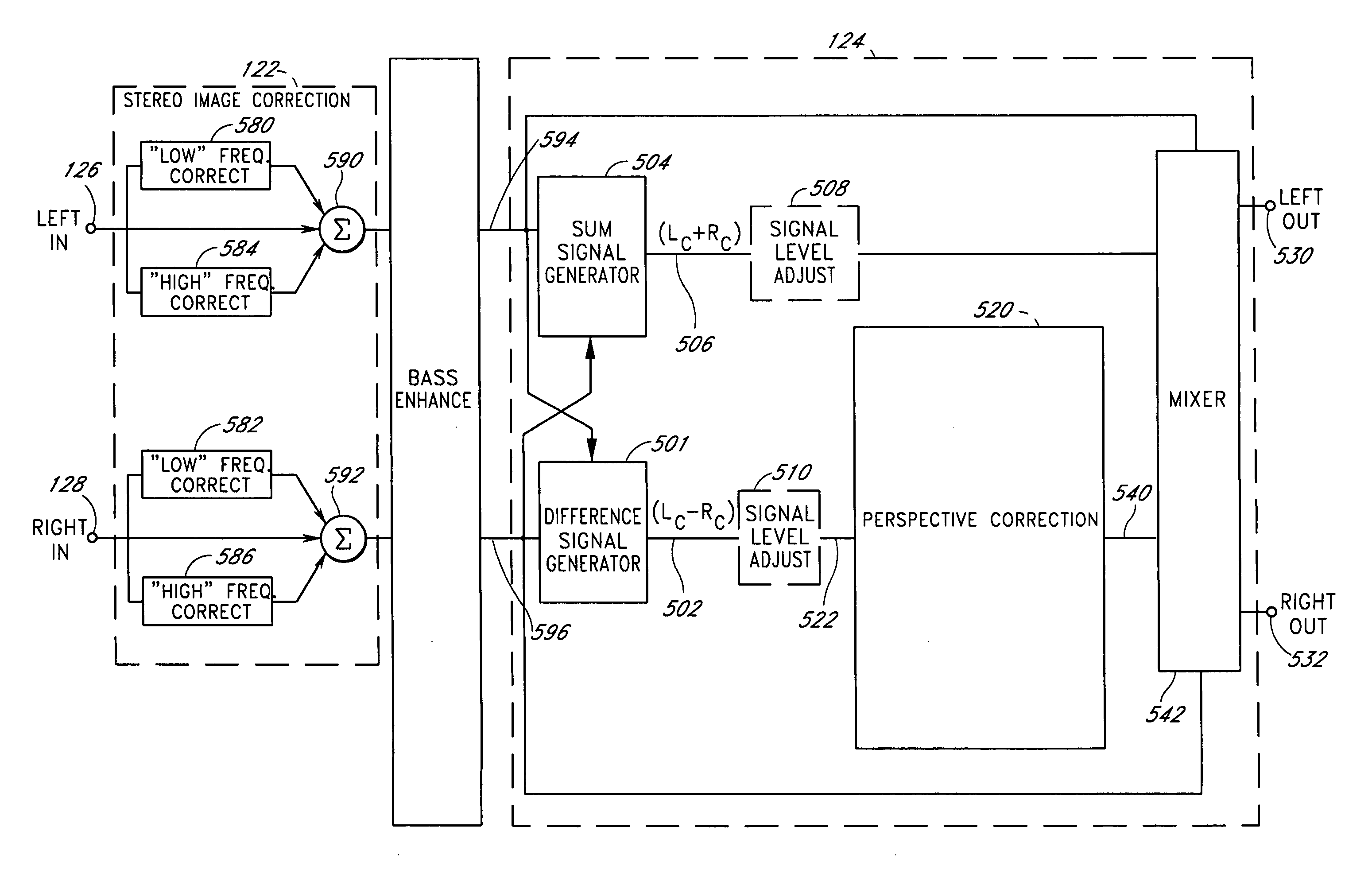
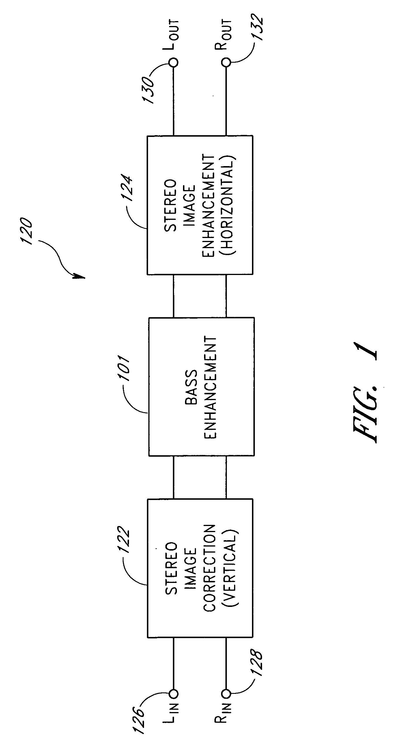
[0108]FIG. 1 is a block diagram of an acoustic correction apparatus 120 comprising, in series, a stereo image correction system 122, a bass enhancement system 101, and a stereo image enhancement system 124. The image correction system 122 provides a left stereo signal and a right stereo signal to the bass enhancement unit 101. The bass enhancement unit outputs left and right stereo signals to respective left and right inputs of the stereo image enhancement device 124. The stereo image enhancement system 124 processes the signals and provides a left output signal 130 and a right output signal 132. The output signals 130 and 132 may in turn be connected to some other form of signal conditioning system, or they may be connected directly to loudspeakers or headphones (not shown).

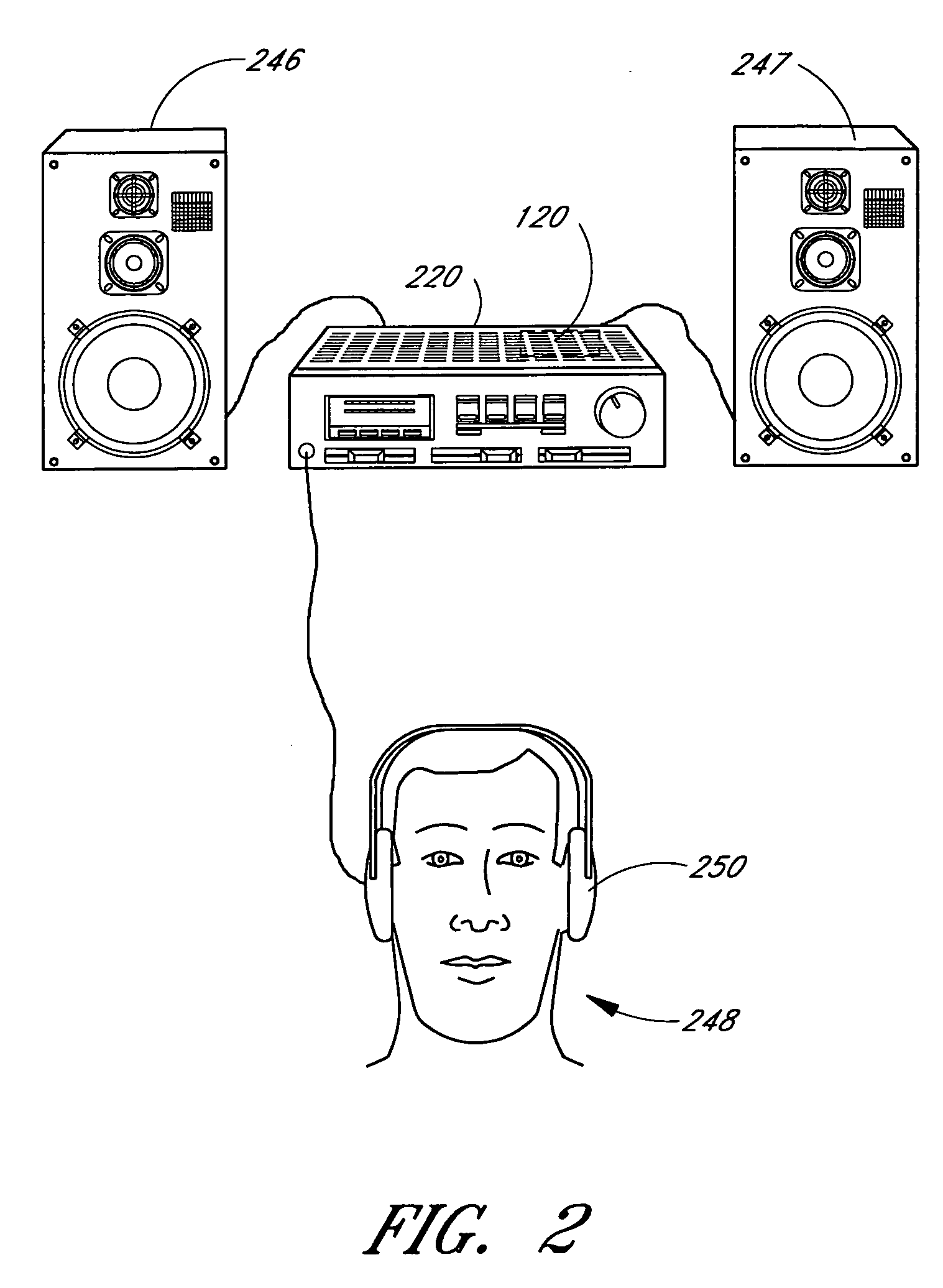
[0109] When connected to loudspeakers, the correction system 120 corrects for deficiencies in the placement of the loudspeakers, the image created by the loudspeakers, and the low frequency response produced by...


PUM


Abstract

An acoustic correction apparatus processes a pair of left and right input signals to compensate for spatial distortion as a function of frequency when said input signals are reproduced through loudspeakers in a sound system. The sound-energy of the left and right input signals is separated and corrected in a first low-frequency range and a second high-frequency range. The resultant signals are recombined to create image-corrected audio signals having a desired sound-pressure response when reproduced by the loudspeakers in the sound system. The desired sound-pressure response creates an apparent sound image location with respect to a listener. The image-corrected signals can also be spatially-enhanced to broaden the apparent sound image and improve the low frequency characteristics of the sound when played on small loudspeakers.

Description

[0001] This application is a continuation of U.S. patent application Ser. No. 09 / 411,143, filed on Oct. 4, 1999, the entirety of which is hereby incorporated herein by reference.FIELD OF THE INVENTION [0002] This invention relates generally to audio enhancement systems, and especially those systems and methods designed to improve the realism of stereo sound reproduction. More particularly, this invention relates to an apparatus for overcoming the acoustic imaging and frequency response deficiencies of a sound system as perceived by a listener. BACKGROUND OF THE INVENTION [0003] In a sound reproduction environment, various factors may serve to degrade the quality of reproduced sound as perceived by a listener. Such factors distinguish the sound reproduction from that of an original sound stage. One such factor is the location of loudspeakers in a sound stage, which, if inappropriately placed, may lead to a distorted sound-pressure response over the audible frequency spectrum. The pla...

Claims


Application Information

Patent Timeline
Patent Type & Authority Applications(United States)
IPC IPC(8): H04R5/00H03G5/00H04R5/033H04S1/00
CPCH04S1/005H04S7/301H04R3/04
Inventor YUEN, THOMAS C.K.KRAEMER, ALAN D.OLIVER, RICHARD
Owner DTS
Why Eureka
Try Eureka