Drive mechanism for camera

Inactive Publication Date: 2006-06-15
PENTAX RICOH IMAGING CO LTD
View PDF13 Cites 19 Cited by
  • Summary
  • Abstract
  • Description
  • Claims
  • Application Information

AI Technical Summary

Benefits of technology

[0009] The present invention provides a drive mechanism for a camera which is smaller and less expensive and can move

Problems solved by technology

Under these circumstances, it is difficult to miniaturize the digital camera if the electromagnetic drive device is used,
Furthermore, the voice coil which is large in size, is also heavy.
Therefore, it is difficult to mo

Method used


Image

  • Drive mechanism for camera
  • Drive mechanism for camera
  • Drive mechanism for camera

Examples


Embodiment Construction

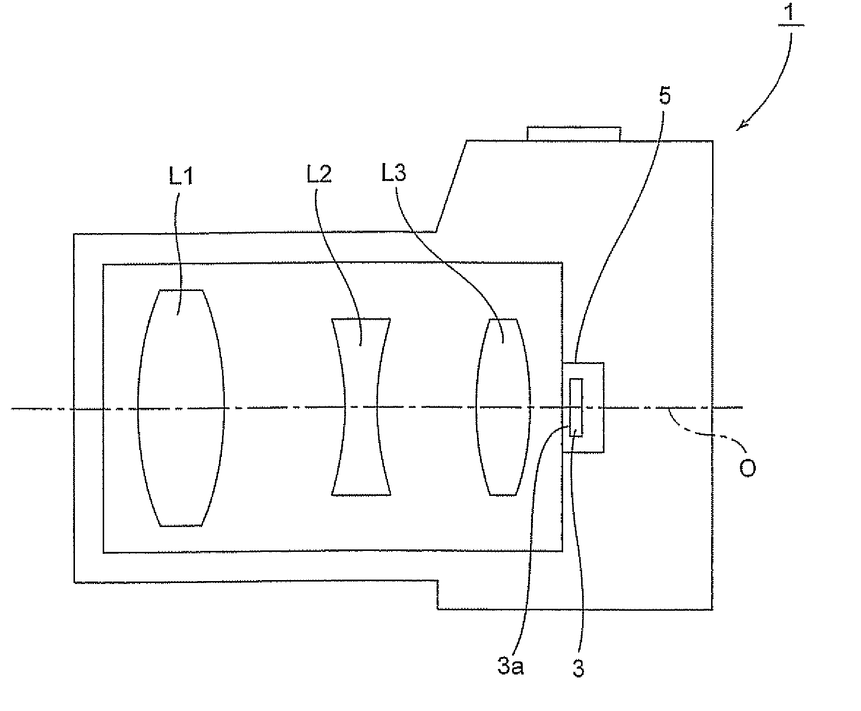
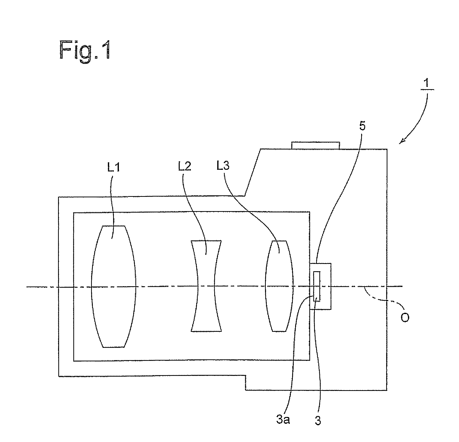
[0049] As shown in FIG. 1, a digital camera 1 has an optical system (photographing lens system) including a plurality of lenses L1, L2, and L3, in a camera body (immovable member). A CCD (image pickup device) 3 is provided behind the lens L3. The CCD 3 has an image pickup surface 3a perpendicular to the optical axis O of the optical system and is secured to a CCD drive mechanism 5 incorporated in the digital camera (camera body / immovable member) 1.

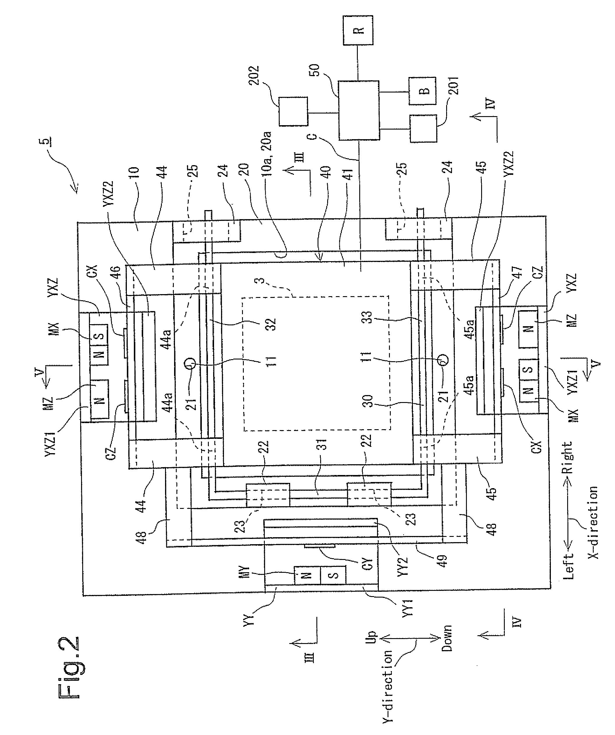
[0050] The CCD drive mechanism (magnetic drive mechanism) 5 is provided with an AF (Auto-focus) function and a camera shake correcting function and is constructed as shown in FIGS. 2 through 18. As can be seen in FIGS. 2 through 6, a stationary support plate 10, which is square in shape as viewed from the rear side thereof and is provided at its center portion with a square receiving hole 10a, is secured to the camera body of the digital camera 1 by a securing device (not shown), so that the support plate 10 is perpendicular to the optica...


PUM


Abstract

A drive mechanism for a camera includes a movable member located behind a photographing lens and linearly moved along an optical axis thereof, the movable member supporting an image pickup device; an AF coil secured to the movable member or an immovable member of the camera; a magnetic force generating device which is secured to the other of the movable member and the immovable member, so as to linearly move the movable member in the optical axis direction relative to the immovable member by applying a magnetic field upon the AF coil; and a controller which controls the direction of electric current flowing in the AF coil so that image light transmitted through the photographing lens is converged onto an image pickup surface of the image pickup device. The AF coil is a planar coil which is wound on a plane parallel with the optical axis.

Description

BACKGROUND OF THE INVENTION [0001] 1. Field of the Invention [0002] The present invention relates to a drive mechanism for a camera, such as an AF mechanism or a camera shake correction mechanism. [0003] 2. Description of the Related Art [0004] In an example of a known AF mechanism of a digital camera, a CCD (image pickup device) is moved in an optical axis direction in accordance with contrast information of image data of an object image picked-up by the CCD, so that the image light transmitted through a photographing lens is always converged onto an image pickup surface of the CCD (e.g., Japanese Unexamined Patent Publication No. 8-154196). [0005] In this AF mechanisms a driving device is used as an electromagnetic drive device to move the CCD in the optical axis direction. Specifically, a permanent magnet is provided on the camera body side, a substantially cylindrical yoke is provided on the camera body side and which is located inside the permanent magnet, and a cylindrical voi...

Claims


Application Information

Patent Timeline
IPC IPC(8): G03B17/00
CPCG02B7/102G02B27/646G03B17/02G03B17/28H04N5/2254H04N5/23248H04N5/23287H04N23/55H04N23/67H04N23/68H04N23/687
Inventor SEO, SHUZO
Owner PENTAX RICOH IMAGING CO LTD
Why Eureka
Try Eureka