System and method for concrete slab connection

a concrete and system technology, applied in the direction of roads, manufacturing tools, roads, etc., can solve the problems of problems such as cracking of the concrete slab, damage to the joints or joints between adjacent sections, etc., to achieve the effect of reducing the amount of labor required and fast and cleaner drilling

Inactive Publication Date: 2006-06-15
ILLINOIS TOOL WORKS INC
View PDF6 Cites 18 Cited by
  • Summary
  • Abstract
  • Description
  • Claims
  • Application Information

AI Technical Summary

Benefits of technology

[0010] An object of the instant invention is to provide a system and method for doweling in existing concrete that is faster and cleaner than drilling. Another object of the instant invention is to provide a system and method for positioning planar dowels into existing concrete. Yet another object of the instant invention is to provide a system and method for utilizing planar dowels with metal forms in new concrete applications. Still another object of the instant invention is to provide a system and method for properly aligning planar dowels in a slab. Another object of the instant invention is to provide a system and method for utilizing planar dowels in a slab that minimizes the amount of labor required during new concrete pours.
[0013] Although vibration of the concrete is necessary for the adjacent slab, roughly half the amount of vibration-related labor is utilized in connection with the system and method of the instant invention as is required by systems of the prior art. This is because vibration labor is only utilized on the adjacent slab, as opposed to both slabs as is necessary in the prior art systems. Cutting into an existing, hardened, slab and placement of a dowel in the cut-away, eliminates the need for vibration in the first slab.
[0014] In a preferred embodiment of the instant invention the saw is self-guided by a control unit that moves across the top of the slab following the slab edge. The saw can be adjusted to provide a series of spaced-apart cuts along the edge of the slab. In another preferred embodiment, the saw will include a mist system to eliminate dust created as the concrete is cut. Such a system is ideal for interior use of the inventive system.
[0015] In a preferred embodiment of the instant invention rubber gaskets, or seal spacers, are connected to the dowel to aid in alignment of the dowel in the cutaway in the slab and to prevent concrete slurry from migrating into the cutaway area in which the dowel is located as the adjacent slab is poured.
[0017] The system and method of the instant invention provides a means for positioning planar dowels into a retrofit application that is much faster and cleaner than the systems of the prior art. Sawing into a slab of concrete is much faster than drilling. In addition, the use of a wet saw device greatly reduces the amount of dust created during installation. In addition, the system of the instant invention allows the use of any type of forms, whether wood, metal or otherwise, as there is no need to nail sheaths to the forms prior to pouring of the slab. Furthermore, the instant invention eliminates the possibility of misalignment of dowels caused by improper form alignment or by accidental dislocation of dowel mounting sheaths as the slab is poured. This is accomplished by cutting into the slab after the slab has hardened. The angle and position of the cut is gauged by the actual surface of the slab, providing ideal alignment of the dowel with respect to the slab surface.

Problems solved by technology

One problem that can arise when slabs are poured in separate subsections is that the junctions or joints between adjacent sections are subject to damage from downward forces exerted against the slab.
If the dowels are not installed correctly, problems can arise.
Specifically, if the dowels are not parallel to the slab surface and perpendicular to the joint between the slab sections, unwanted stresses can be created in the slab, which can lead to cracking of the slab.
Notwithstanding, the noted disadvantages of tubular dowels versus planer dowels, drilling in existing concrete is extremely time consuming and creates considerable dust which is undesirable for interior retrofit applications.
A disadvantage of prior art systems and methods of utilizing planar dowels in new concrete pours in which a sheath is embedded in a slab, is that only wooden forms can be used for forming the slab.
Another disadvantage of prior art systems for locating planar dowels in a slab is that attachment of the sheath to the form requires extremely careful positioning of the sheath with respect to the top edge of the form as well as extremely careful leveling of the form at the location in which the slab edge is to be made.
Even slight misalignment of either the sheath or of the form board will result in misalignment of the dowel with the slab and can result in undesired stresses in the slab.
Misalignment or dislocation of the sheaths can result after the sheath has been mounted to the form either as the form is being positioned or after the form is in position by workers accidentally stepping on the sheaths or bumping against the sheaths.
Misalignment of the form board can also result from workers accidentally kicking the form board, or misalignment can be the result of a warped form board.

Method used


Image

  • System and method for concrete slab connection
  • System and method for concrete slab connection
  • System and method for concrete slab connection

Examples


Embodiment Construction

[0028] As required, a detailed embodiment of the present inventions is disclosed herein; however, it is to be understood that the disclosed embodiment is merely exemplary of the principles of the invention, which may be embodied in various forms. Therefore, specific structural and functional details disclosed herein are not to be interpreted as limiting, but merely as a basis for the claims and as a representative basis for teaching one skilled in the art to variously employ the present invention in virtually any appropriately detailed structure.

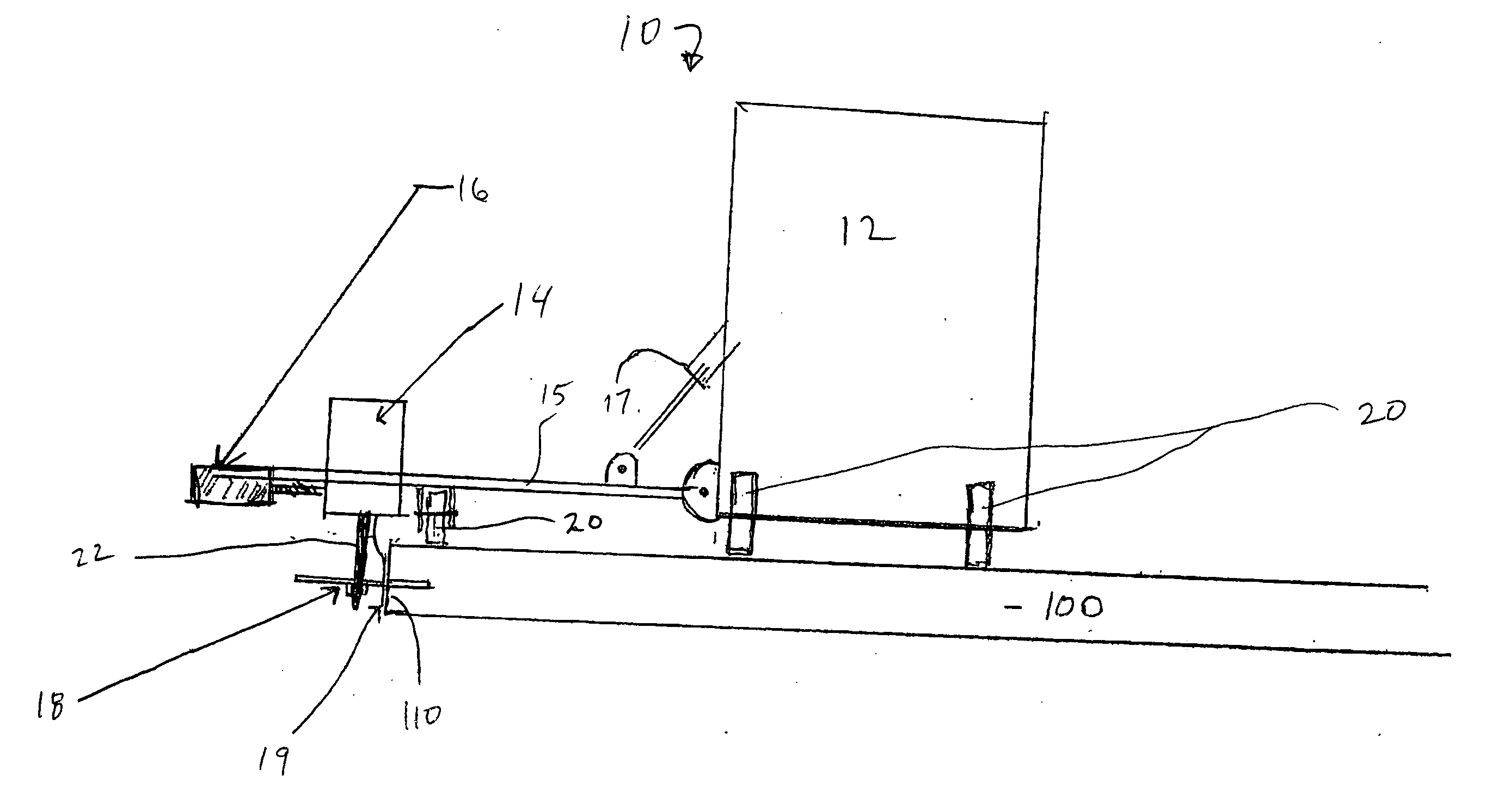
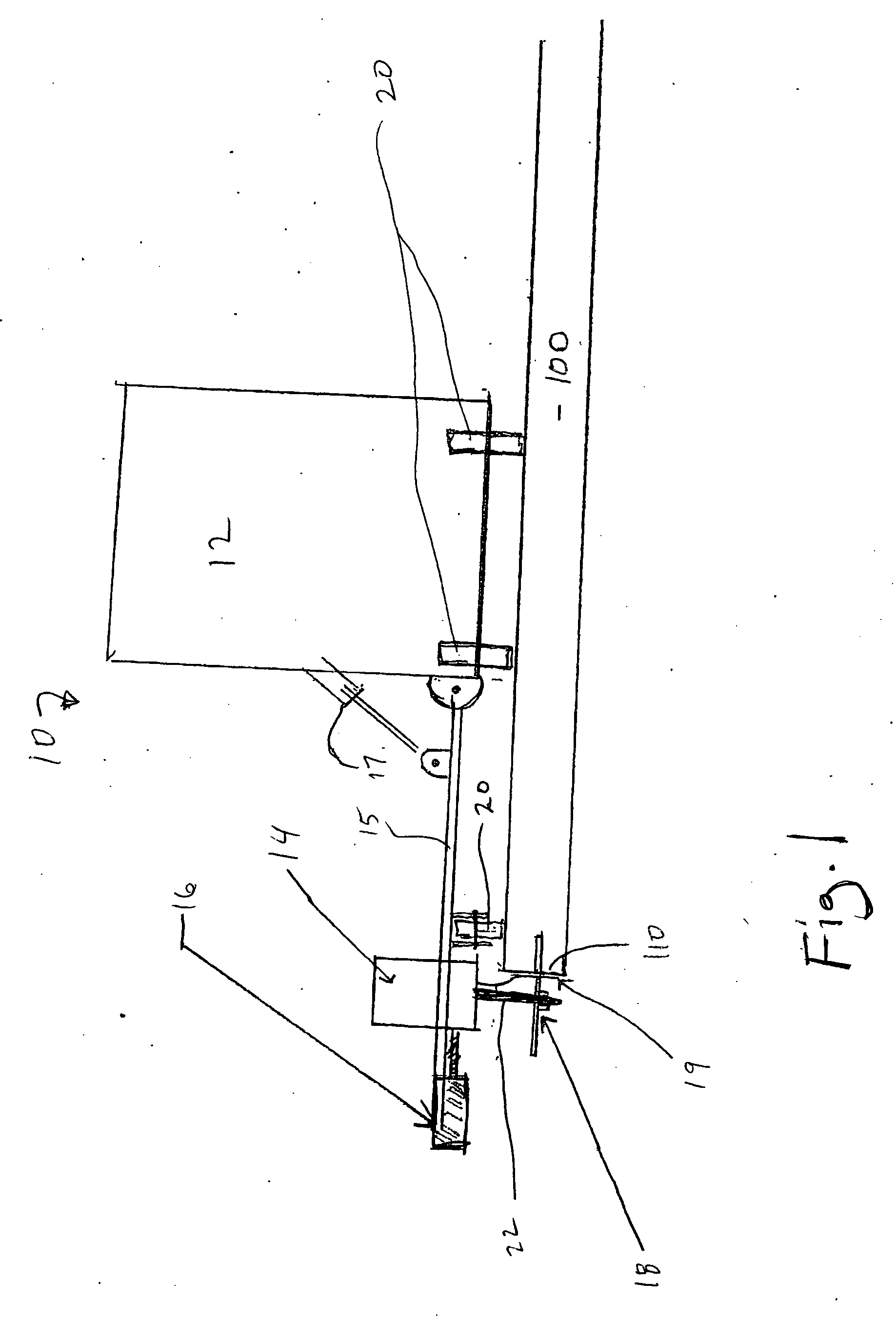
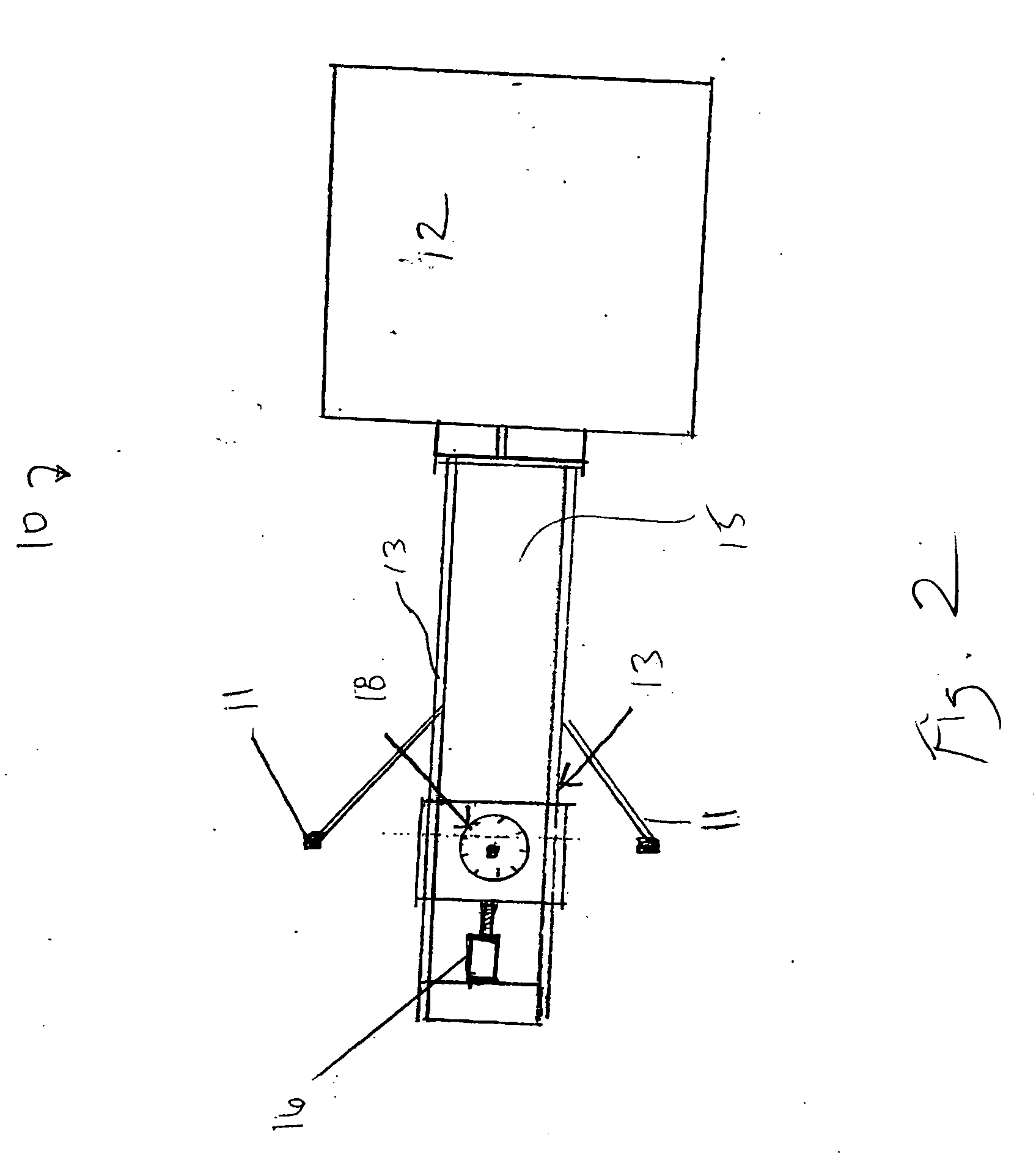
[0029] Referring to FIGS. 1 and 2, a plunge-cut saw unit (10) of the instant invention is shown. As shown in FIG. 1, saw unit 10 travels over the top of preexisting concrete slab 100 on wheels 20 following edge 110 of slab 100. The height of cutting blade 18 is adjustable to control the vertical depth at which the cut is made into slab 100 by raising and lowering mechanism (not shown) which raises and lowers drive unit 14 along with saw bla...


PUM

PropertyMeasurementUnit
shapeaaaaaaaaaa
heightaaaaaaaaaa
strengthaaaaaaaaaa

Abstract

Systems and methods of transferring loads between adjacent cast-in-place slabs, such as concrete slabs, and for accurately positioning dowels between adjacent sections of slabs are provided. A generally planar plate-type dowel is used which may be positioned within a cutaway in a preexisting slab of concrete. The dowel is shaped to generally conform to the shape of the cutaway, which is made by a saw blade. Once the dowel is positioned within the preexisting slab, a new slab is poured adjacent the preexisting slab. Rubber seals are included on the edges of the dowels to provide spacing or a gap between the dowel and the preexisting slab to allow for lateral independent movement of the adjacent slabs, and to prevent concrete from the newly poured second slab from entering into the gap. A saw unit for making a generally planar cut horizontally into an edge of a hardened concrete slab is also provided.

Description

[0001] This application claims priority pursuant to 35 U.S.C. 119(e) to co-pending U.S. Provisional Patent Application Serial No. 60 / 578,512, filed Jun. 10, 2004, the entire disclosure of which is incorporated herein by reference.FIELD OF THE INVENTION [0002] The present inventions relate generally to systems and methods for pavement reinforcement. More particularly, the present inventions are concerned with systems and methods of transferring loads between adjacent cast-in-place slabs, such as concrete slabs, and for accurately positioning dowels between adjacent sections of slabs. BACKGROUND OF THE INVENTION [0003] In the construction of concrete floors or surfaces (i.e. sidewalks, driveways, roads, etc.), it has long been the practice to make the surface from a series of individual blocks or slabs. Adjacent slabs meet each other at joints which are typically spaced so that each slab has enough strength to overcome internal stresses that would otherwise cause random stress relief ...

Claims


Application Information

Patent Timeline
Patent Type & Authority Applications(United States)
IPC IPC(8): E01C11/02
CPCE01C11/14E01C23/04B28D1/045E04C5/12B28D1/02
Inventor NADLER, DONALD S.
Owner ILLINOIS TOOL WORKS INC
Why Eureka
Try Eureka