
Apparatus and method for mounting a cardiac harness on the heart

a cardiac harness and apparatus technology, applied in the field of heart failure devices, can solve the problems of limiting the versatility of the cup, the device and method for delivering and positioning the cardiac harness onto the heart of a patient's heart has yet to be provided, and it is difficult to maintain a vacuum or suction on the heart tissue of a beating heart with a rigid suction cup, so as to achieve the effect of increasing the flexibility of the cup body

Inactive Publication Date: 2006-06-15
PARACOR MEDICAL
View PDF99 Cites 18 Cited by
  • Summary
  • Abstract
  • Description
  • Claims
  • Application Information

AI Technical Summary

Benefits of technology

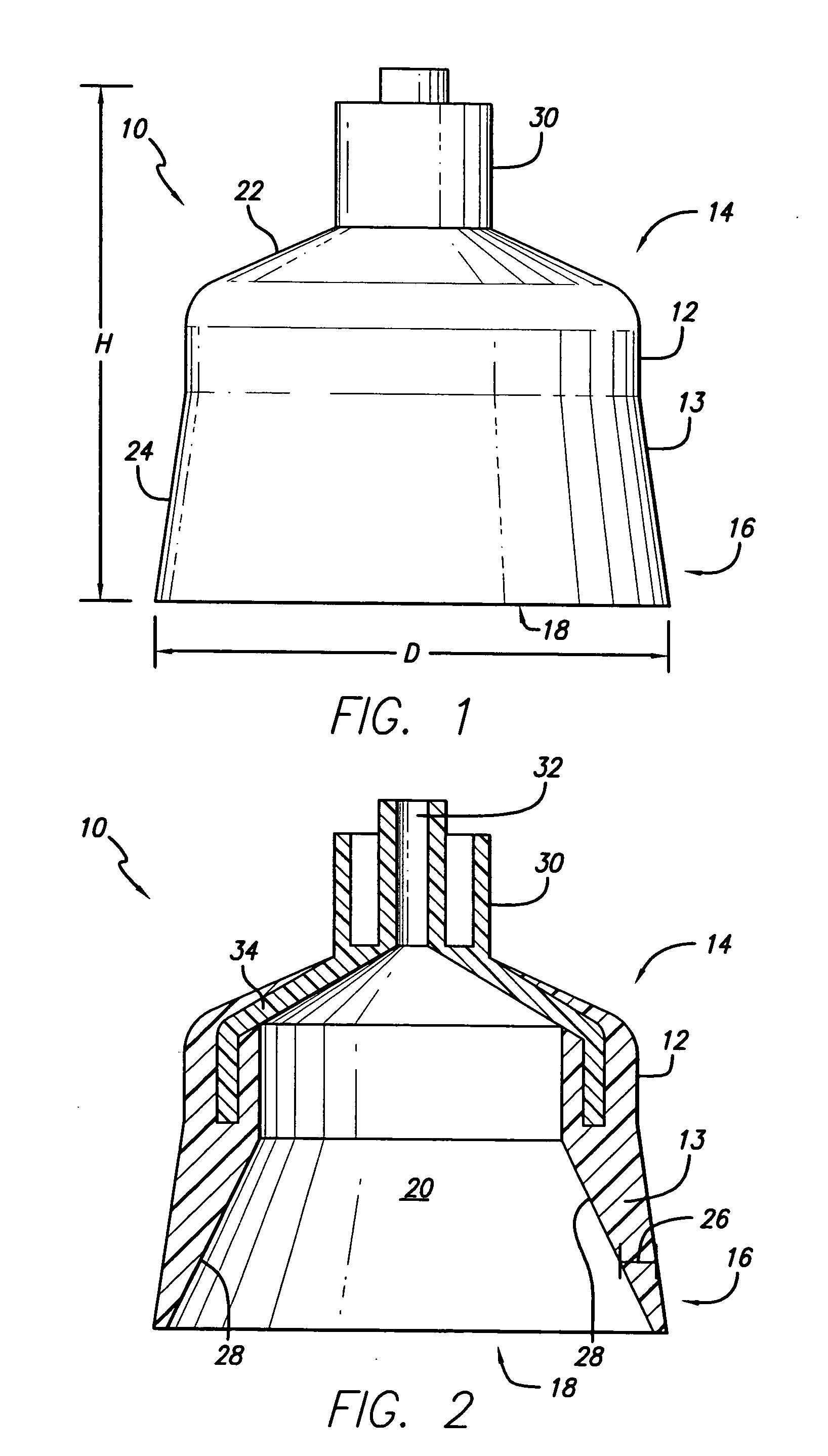
[0008] One method of forming a suction cup of the present invention includes placing a rigid connecting aperture in a mold and then casting a pourable silicone rubber around the rigid connecting aperture to form a cup body. The cup body is generally bell shaped, and the lower portion of the cup body can define an opening that is circular, elliptical, or any other shape that is desirable for attaching to the heart. In general, the outside surface of the cup body includes at least one taper, and the lower portion of the cup body flares radially outward. The suction cup is also formed so that a wall of the cup body having a radial width includes a taper. In one embodiment, the radial width of the wall tapers down towards the opening of the cup body on the inside surface of the cup body, thereby increasing the flexibility of the cup body near the opening.

Problems solved by technology

While advances have been made in cardiac harness technology, a satisfactory device and method for delivering and positioning the cardiac harness onto a patient's heart has yet to be provided.
The rigidness of the suction cup limits its versatility and may present problems with the deployment of a cardiac harness.
Further, it may be difficult to maintain a vacuum or suction on the heart tissue of a beating heart with a rigid suction cup.
There may also be a problem with the rigid suction cup in that it is not able to conform to the shape of the individual patient's heart.

Method used


Image

  • Apparatus and method for mounting a cardiac harness on the heart
  • Apparatus and method for mounting a cardiac harness on the heart
  • Apparatus and method for mounting a cardiac harness on the heart

Examples


Embodiment Construction

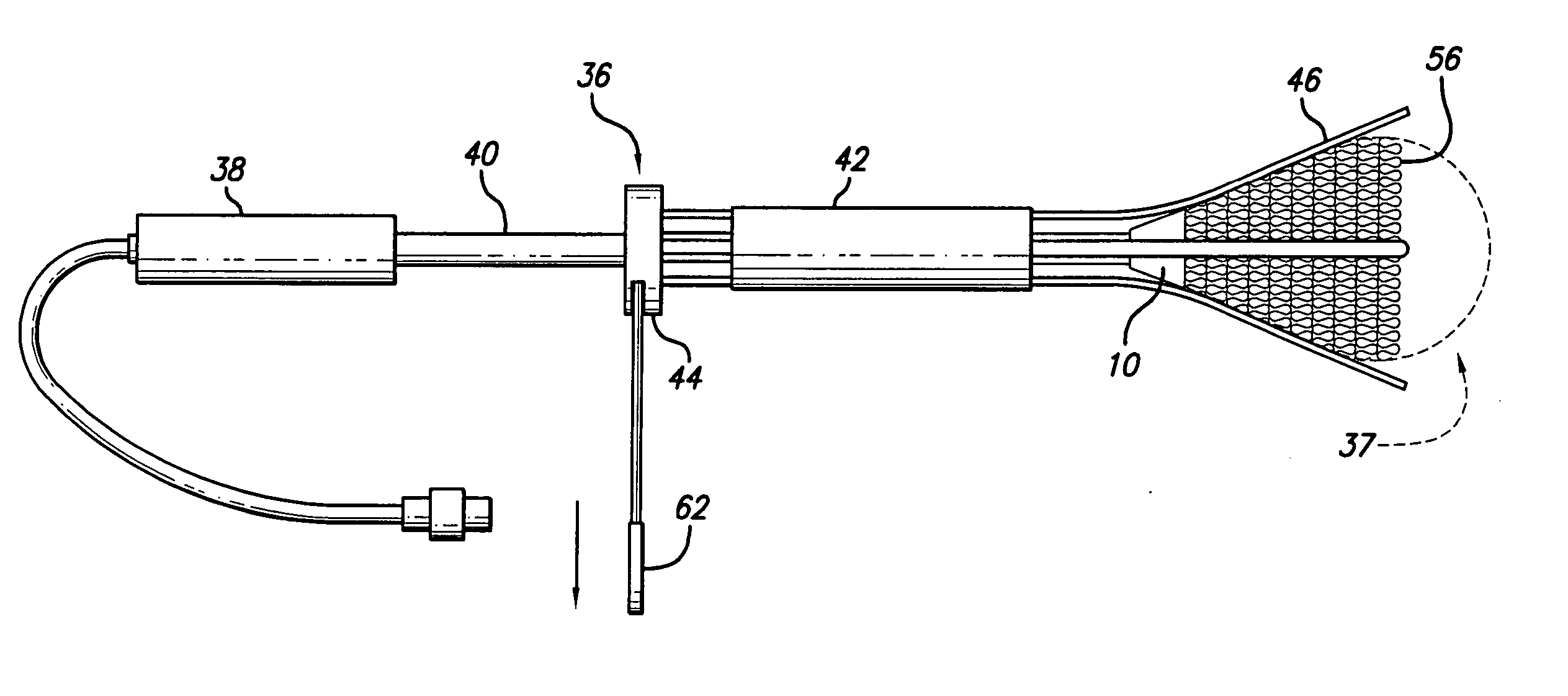
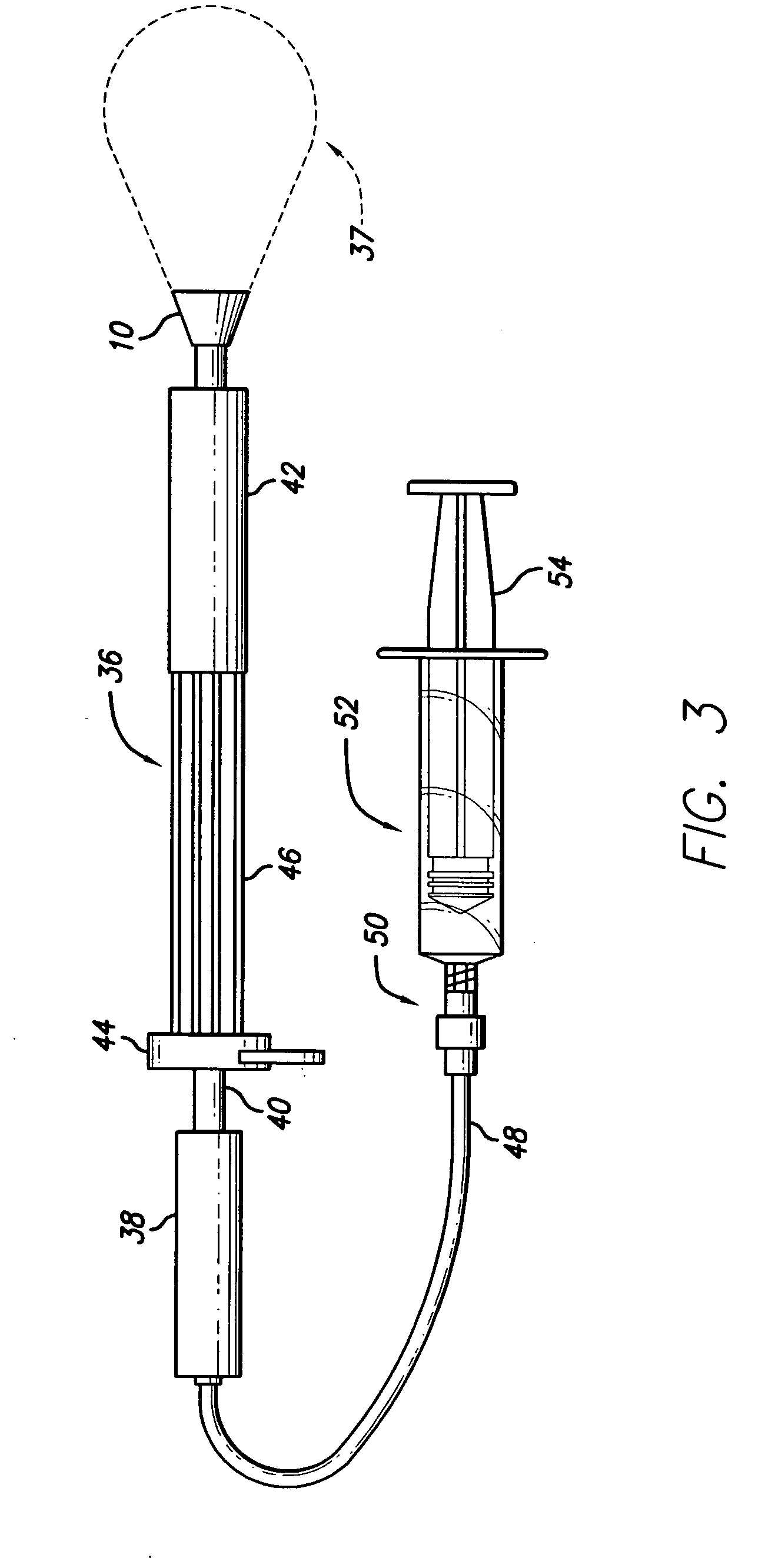
[0028] One embodiment is directed to a suction cup for use with a delivery device for delivering a cardiac harness to a beating heart. The suction cup is associated with the delivery device and is used to attach at the apex of the heart to maintain the position of the delivery device with respect to the heart. Once the suction cup is placed on the heart, air is withdrawn from an inner area of the suction cup to create a vacuum, thereby permitting the suction cup to securely hold the beating heart of a patient. The suction cup can then be pulled in a proximal direction away from the heart to counteract the deployment forces required to deliver and advance a cardiac harness over the heart.

[0029] Referring to FIGS. 1 and 2, one embodiment of a suction cup 10 includes a cup body 12 having a wall 13. The cup body is formed of a flexible material, preferably silicone rubber. However, any soft and playable material may be used, including any thermoplastic elastomers or rubbers, such as kr...


PUM

PropertyMeasurementUnit
diameteraaaaaaaaaa
diameteraaaaaaaaaa
diameteraaaaaaaaaa

Abstract

A suction cup for use with a delivery device for delivering a cardiac harness to a heart. The suction cup includes a cup body formed of a flexible material, such as silicone, and the cup body has an upper portion and a lower portion, wherein the lower portion defines an opening leading to an inner area of the cup body. The suction cup also includes a connecting aperture formed of a rigid material that is attached to the upper portion of the cup body. The flexible material of the cup body allows the suction cup to rotate relative to the heart tissue, and to re-center itself onto the apex of the heart when the suction cup is improperly aligned with the apex, all while preserving a vacuum attachment to the heart.

Description

BACKGROUND OF THE INVENTION [0001] 1. Field of the Invention [0002] The present invention relates to a device for treating heart failure. More specifically, the invention relates to a suction cup configured to attach to the apex of the heart to counteract the deployment forces required to advance a cardiac harness over the heart. [0003] 2. General Background and State of the Art [0004] Congestive heart failure (“CHF”) is characterized by the failure of the heart to pump blood at sufficient flow rates to meet the metabolic demand of tissues, especially the demand for oxygen. It has been determined that a passive wrap, or cardiac harness, may increase the efficiency of a heart affected by congestive heart disease. While advances have been made in cardiac harness technology, a satisfactory device and method for delivering and positioning the cardiac harness onto a patient's heart has yet to be provided. [0005] Present cardiac harness delivery assemblies use a rigid suction cup to attac...

Claims


Application Information

Patent Timeline
Patent Type & Authority Applications(United States)
IPC IPC(8): A61F2/00B28B1/14
CPCA61F2/2481A61F2002/2484B29C70/766B29K2083/00B29L2031/7546
Inventor WALLIN, JOSHUAPALMA, CHRISTINE
Owner PARACOR MEDICAL
Learn More