Eureka AIR delivers breakthrough ideas for toughest innovation challenges, trusted by R&D personnel around the world.

Filter column module

a filter column and module technology, applied in the field of filter column modules, can solve the problems of high throughput system, inconvenient automatic technology, and inability to recover samples, and achieve the effect of increasing the sample recovery ra

Inactive Publication Date: 2006-06-22
IND TECH RES INST
View PDF21 Cites 0 Cited by
  • Summary
  • Abstract
  • Description
  • Claims
  • Application Information

AI Technical Summary

Benefits of technology

[0007] The filter column module of the present invention utilizes a vacuum pumping system instead of a centrifugal system, and so may be applied in an automatic apparatus. Additionally, the filter column module of the present invention can increase the sample recovering rate.
[0012] For operational convenience, the filter column module further comprises a loading base with fixing troughs, and the fixing troughs can be arranged in n×m arrays, wherein the n and m are integers not less than 1 such as 96 trough arrays, 192 trough arrays, or 384 trough arrays. The filter column module of the present invention preferably operated by means of vacuum pumping, so an exhaust channel of the loading base is preferably provided. Furthermore, in order to ensure high efficiency of the vacuum pump, an elastic O-ring can be placed between the upper column and the lower column, and between the lower column and the loading base to improve the hermetic seal.
[0014] To improve sealing between the different elements, the upper column and the lower column may have different diameters to provide a sliding combination. The largest diameter of the protruding bottom shell of the upper column is preferably smaller than the top opening of the lower column, so that the protruding bottom shell of the upper column can be placed within the top opening of the lower column. After insertion of the lower column, the support for the lower column partially contacts the protruding bottom shell of the upper column, and a filter can be placed between the lower column support and the protruding bottom shell of the upper column.
[0016] The loading base of the filter column module may be connected to a pump to provide vacuum pumping. To increase tightness between the upper column, the filter and the lower column, the protruding bottom shell of the upper column may have different shaped edges, such as wave-shaped edges or saw tooth-shaped edges.

Problems solved by technology

For bio-sample concentration and purification, the recovering rates of samples are a very important issue.
By using centrifugal technologies, higher recovering rates can be achieved, but this technology is not suitable for automatic, high throughput systems.
As a result, the precious biological samples may remain in the isolating or purifying apparatus, and hence lead to a deficiency in sample volumes.
However, the above-mentioned methods are used in centrifugal systems, and multi-pore filter plates are not suitable for small quantities of samples.

Method used


Image

  • Filter column module
  • Filter column module
  • Filter column module

Examples


embodiment 1

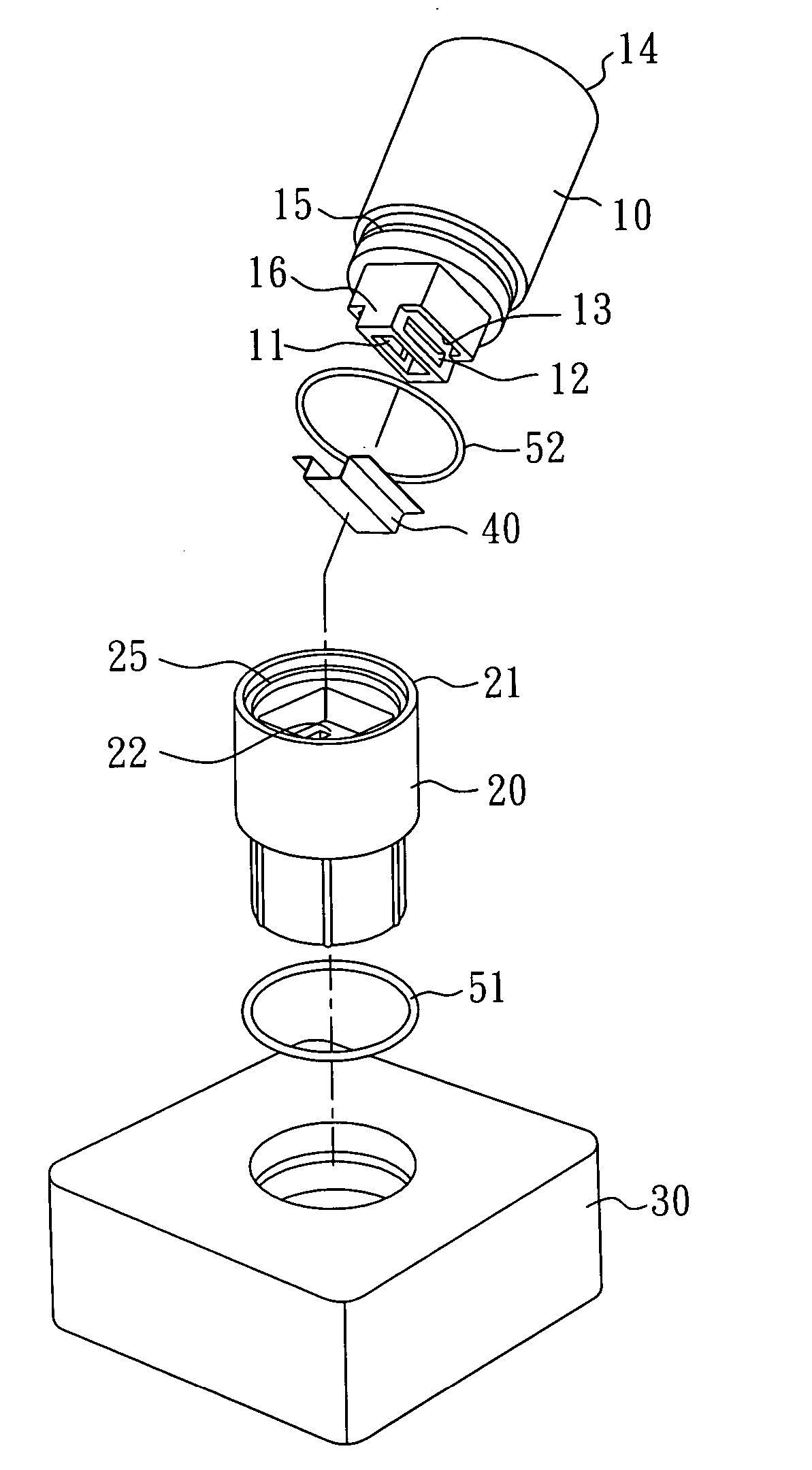
[0022] Please refer to FIG. 1. A filter column module of the present invention has an upper column 10 and a lower column 20. For convenience, a base 30 can be added for emplacement of the lower column 20 to stabilize the entire module.

[0023] The upper column 10 comprises a top opening 14 for the input of samples, and a protruding bottom shell 16 that has a plurality of apertures 11, 12, 13 and two additional apertures (not shown) facing the apertures 12, 13 on each surface of protruding bottom shell 16. Consequently, as shown in the drawing, all five bottom faces on the ladder-shaped protruding bottom shell 16 of the upper column 10 are permeable, which increases the efficiency of the filter.

[0024] With an equal volume of a liquid sample, the height of the liquid surface in the upper column 10 presented in the embodiment with a ladder configuration is greater than that of a traditional round-bottom filter tube, which can reduce residues forming at the bottom and provide higher sam...

embodiment 2

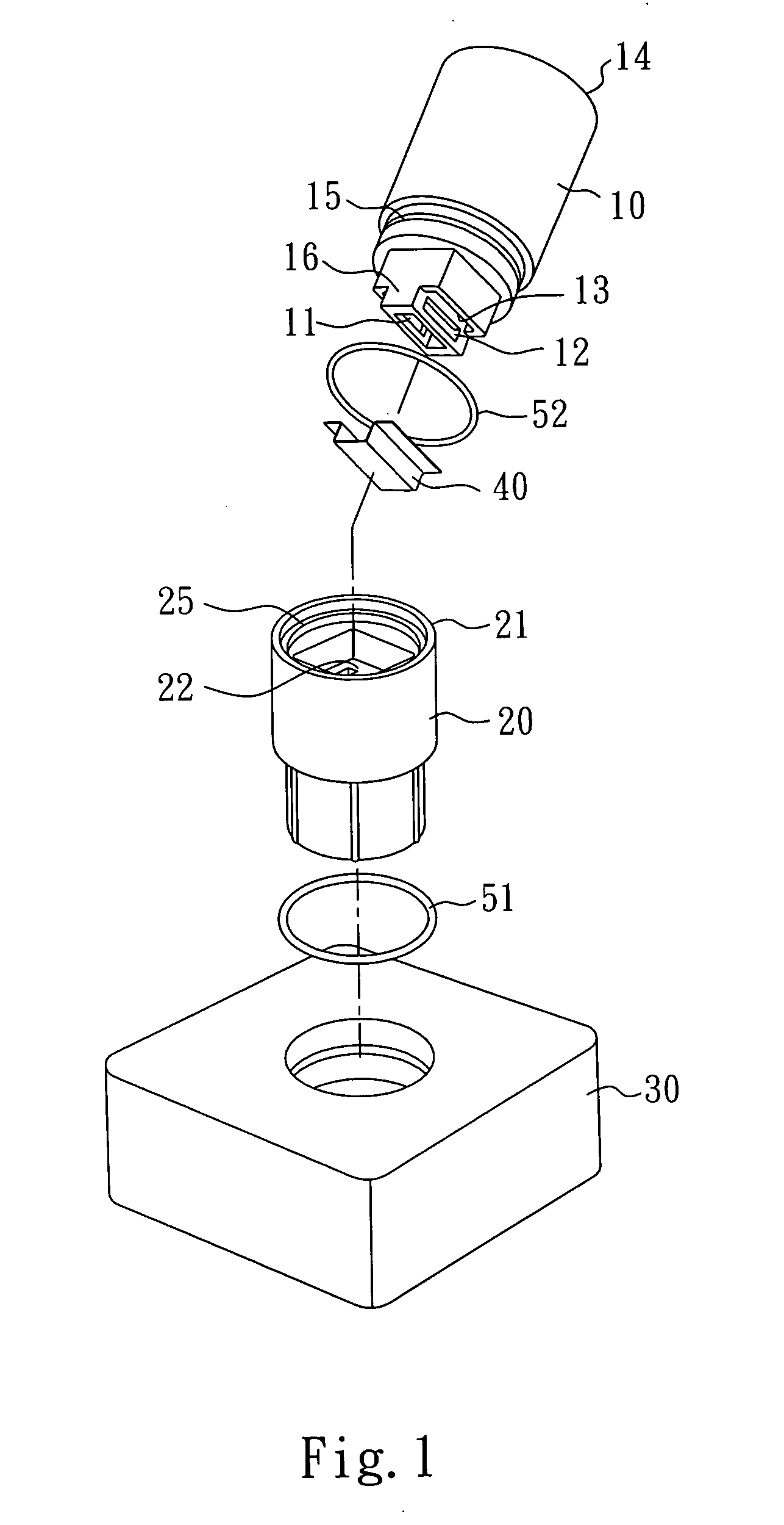
[0029]FIG. 2 shows an upper filter column with a saw-toothed edge. By utilizing the saw-toothed edge 60 on the protruding bottom shell 16, the sieve membrane 40 is provided a better seal at the edge of the column. The edge of the column may have other profiles, such as an undulating shape. Additionally, the upper column and the lower column may also be fastened together by way of a plurality of positioning points 61.

embodiment 3

[0030] As shown in FIG. 3, a bottom of the upper column 10 may have two U-shaped supports 17, 18. These two U-shaped supports 17, 18 impart a friction force on the sieve membrane 40 when the upper column 10 and the lower column 20 are combined together. The bottom of the lower column 20 is a support 22 with holes. When the upper column and the lower column are combined together, the support 22 partially contacts the protruding bottom shell of the upper column to prevent the sieve membrane 40 from breaking under the vacuum pumping.

[0031] An elastic O-ring 52 may be inserted between the lower column 20 and the upper column 10, and a protrusion 15 on the upper column 10 and a groove 25 on the lower column 20 can be mated together. Next, the assembled filter column can be placed in a fixing trough on the base 30, and an elastic O-ring 51 can also be disposed between the column and the base 30.


PUM

PropertyMeasurementUnit
diameteraaaaaaaaaa
flexibleaaaaaaaaaa
frictionaaaaaaaaaa

Abstract

A filter column module is disclosed, which has an upper column having a top opening, and a protruding bottom shell. The bottom shell has a plurality of apertures, and a diameter smaller than that of the upper column. A lower column has a support at the bottom and an opening that accommodates the protruding bottom shell of the upper column. The support partially contacts the protruding bottom shell of the upper column, and liquid or air can pass through the support. A filter is placed between the protruding bottom shell of the upper column and the support of the lower column.

Description

BACKGROUND OF THE INVENTION [0001] 1. Field of the Invention [0002] The present invention relates to a filter column module, and more particularly, to a filter column module for bio-sample concentration and purification. [0003] 2. Description of the Related Art [0004] For bio-sample concentration and purification, the recovering rates of samples are a very important issue. By using centrifugal technologies, higher recovering rates can be achieved, but this technology is not suitable for automatic, high throughput systems. As a result, the precious biological samples may remain in the isolating or purifying apparatus, and hence lead to a deficiency in sample volumes. [0005] Membrane separation technologies have been developed for automatic sample concentration and purification, which may use a single filter tube or a multi-pore filter plate to fasten the membrane by way of heat bonding, ultrasonic bonding or friction bonding. However, the above-mentioned methods are used in centrifug...

Claims


Application Information

Patent Timeline
Patent Type & Authority Applications(United States)
IPC IPC(8): B01D63/00
CPCB01D63/08B01D69/06B01L3/50255B01L3/50855B01L2200/0689B01L2300/0681B01L2300/0829G01N1/40G01N1/4077B01D2313/025B01D69/061B01D63/089
Inventor TSENG, CHING-TAIHUANG, TUNG-LIANG
Owner IND TECH RES INST
Why Eureka
Eureka Blog
Learn More