

Beverage dispenser
a beverage dispenser and dispenser technology, applied in the field of beverage dispensers, can solve the problems of wasting a lot of time and troublesome beverage generation, and achieve the effect of efficient correction of cup stop positions
- Summary
- Abstract
- Description
- Claims
- Application Information
AI Technical Summary
Benefits of technology
Problems solved by technology
Method used
Image

Examples
Embodiment Construction
[0021] FIGS. 1 to 8 show an embodiment of the present invention. The following description indicates top of FIG. 1 as the top, bottom of FIG. 1 as the bottom, left of FIG. 1 as the left, right of FIG. 1 as the right, a front side of FIG. 1 as the front, and a depth side of FIG. 1 as the back.
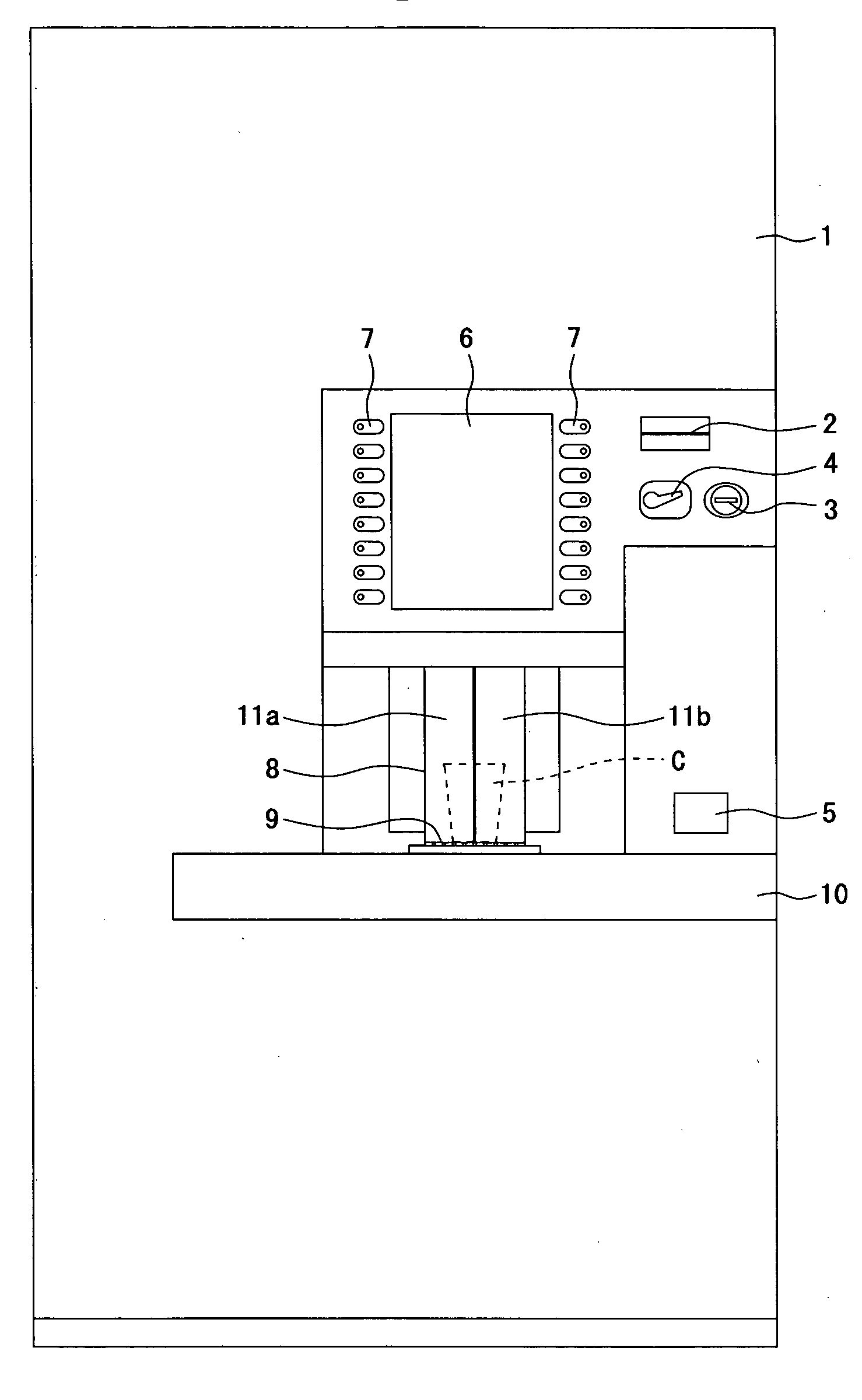
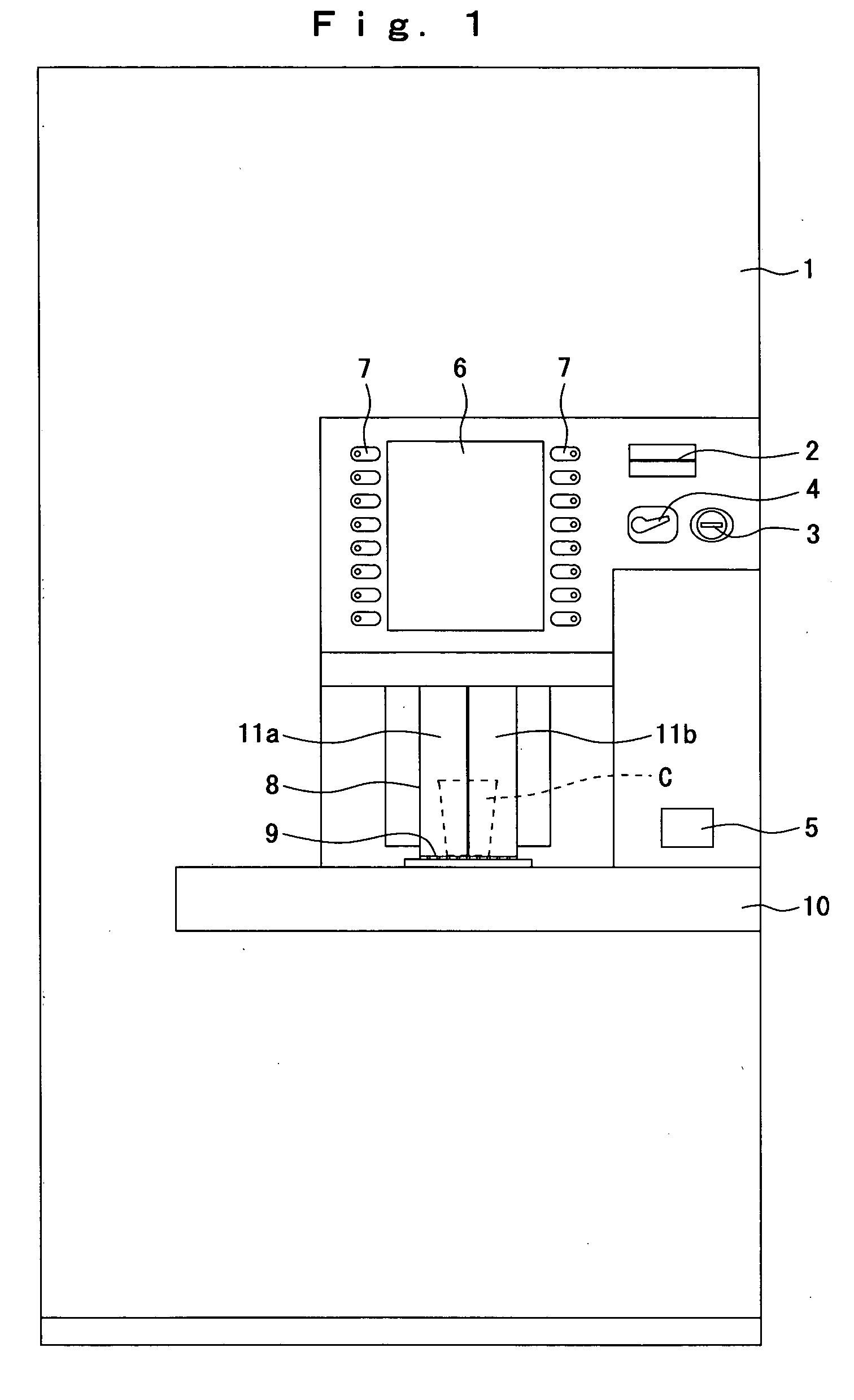
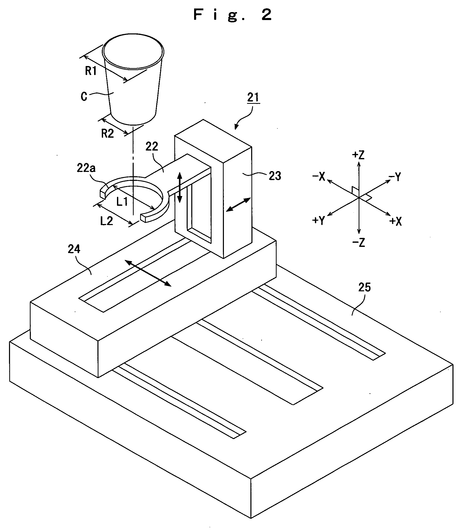
[0022]FIG. 1 is a front view of a beverage dispenser.
[0023] A body 1 comprises a cabinet (not shown) of which a front face is open and a door (no reference numeral) openable and closable provided at a front opening of the cabinet. The body 1 is provided with beverage generating devices (not shown), a straw carrier (not shown) and a cup mover 21 (refer to FIG. 2) described later. The beverage generating devices include a cup carrier, a water cleaner, a hot-water generator, material storehouses, a coffee extractor, an ice maker, an agitator and so on.
[0024] At a front face of the door of the body 1, there are a bill slot 2, a coin slot 3, a return lever 4, a coin return opening 5, a image displ...
PUM
 Abstract
Description
Claims
Application Information