Light emitting apparatus

Inactive Publication Date: 2006-06-22
NICHIA CORP
View PDF3 Cites 37 Cited by
  • Summary
  • Abstract
  • Description
  • Claims
  • Application Information

AI Technical Summary

Benefits of technology

[0052] It is preferable that the third portions of the first and second lead terminals are formed so as to provide an anchor effect. This can prevent the lead terminal from dropping off. Particularly, each third portion of the first and second lead terminals is wide. Accordingly, they can be easily formed so as to provide an anchor effect.
[0053] The securing member can include a window portion having bottom and side surfaces formed therein, and the bottom surface is provided with at least parts of the third portion of the first lead terminal that is provide with the first light emitting element mounted thereon and the third portion of the second lead terminal that is provide with the second light emitting element mounted thereon, wherein the window portion that is encompassed by the bottom and side surfaces is provided with a transparent resin. The refractive index difference between a light emitting element and air is large. In the case where the transparent resin is provided, it is possible to improve the outgoing efficiency of light from the light emitting elements. In addition, it is possible to protect the light emitting elements.
[0054] The transparent resin can include a phosphor material. This can provide a light emitting apparatus with a desired color tone. For example, in the case where a GaN group light emitting element as the first light emitting element that emits blue light, a light emitting element as the second light emitting element that emits red light, and a phosphor material that emits green to yellow luminescent radiation (e.g., a YAG phosphor) are combined, a light emitting apparatus that emits white light can be provided. In this case, it is possible to provide a high-power light emitting apparatus. Moreover, it is possible to provide a light emitting apparatus with less color deviation.
[0055] A light emitting apparatus according to the present invention comprises a first GaN group light emitting element; a second GaN group light emitting element; a first lead terminal with the first light emitting element mounted thereon; a second lead terminal with the second light emitting element mounted thereon; a third lead terminal electrically connected to the first light emitting element; a fourth lead terminal electrically connected to the second light emitting element; and a securing member that secures the first to fourth lead terminals. In the light emitting apparatus, the first lead terminal is composed integrally of a first portion that is electrically connected to an external terminal, a second portion that is exposed from the securing member and a third portion that is provide with the first light emitting element mounted

Problems solved by technology

There is a problem that this heat may damage the third light emitting element 3130.
Particularly, in consideration of power

Method used


Image

  • Light emitting apparatus
  • Light emitting apparatus
  • Light emitting apparatus

Examples


first embodiment

(Light Emitting Apparatus)

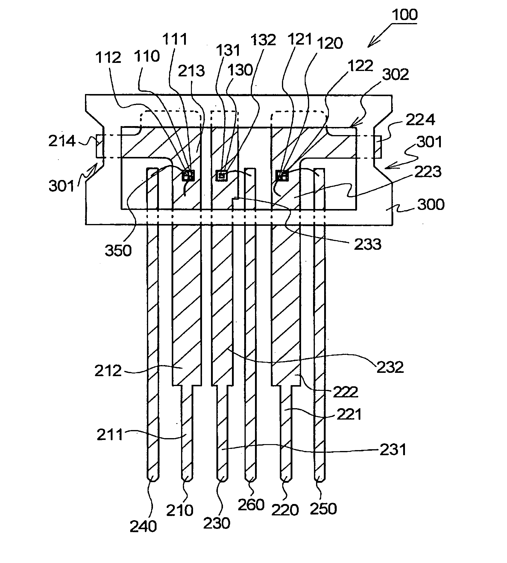
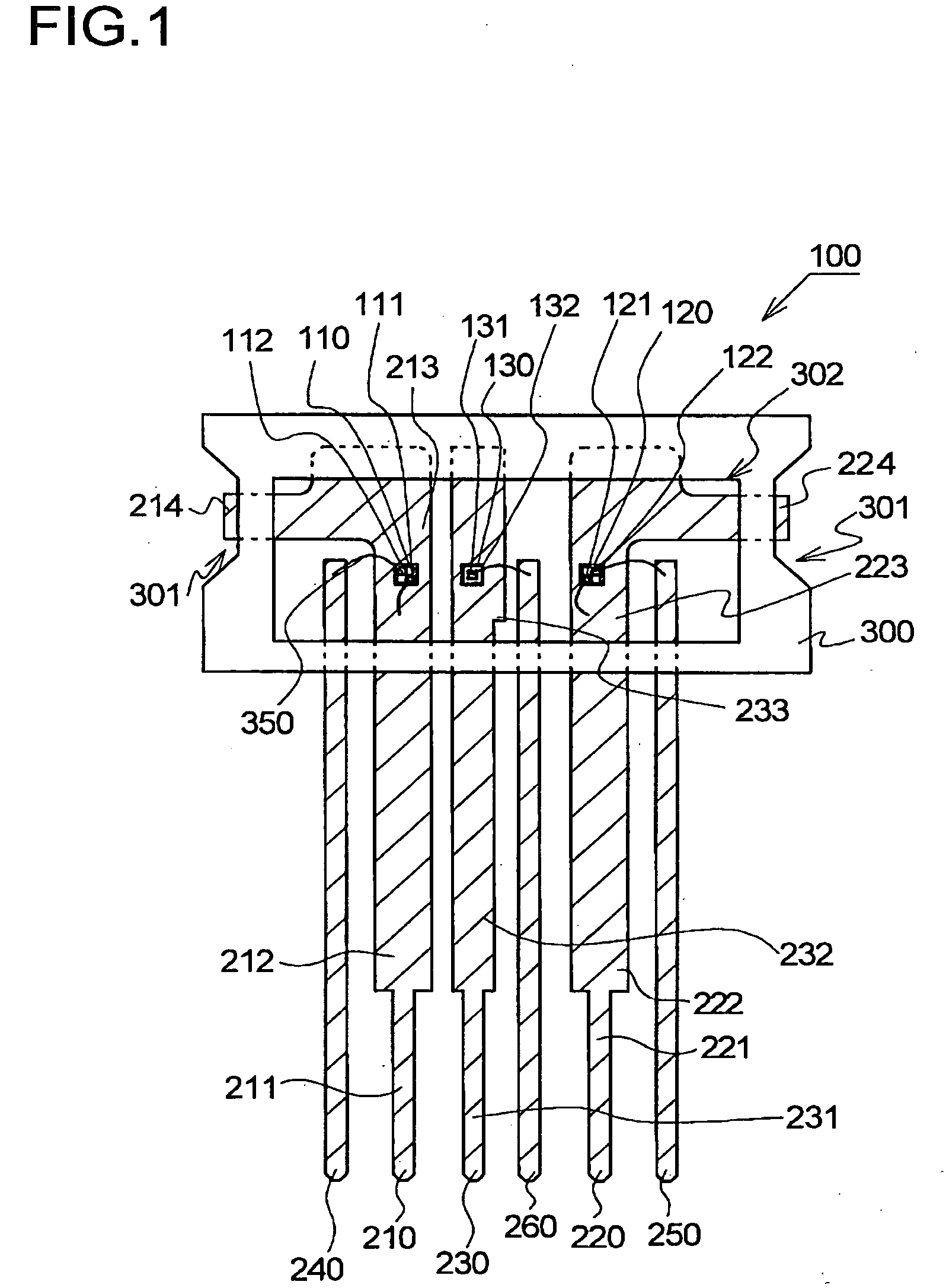
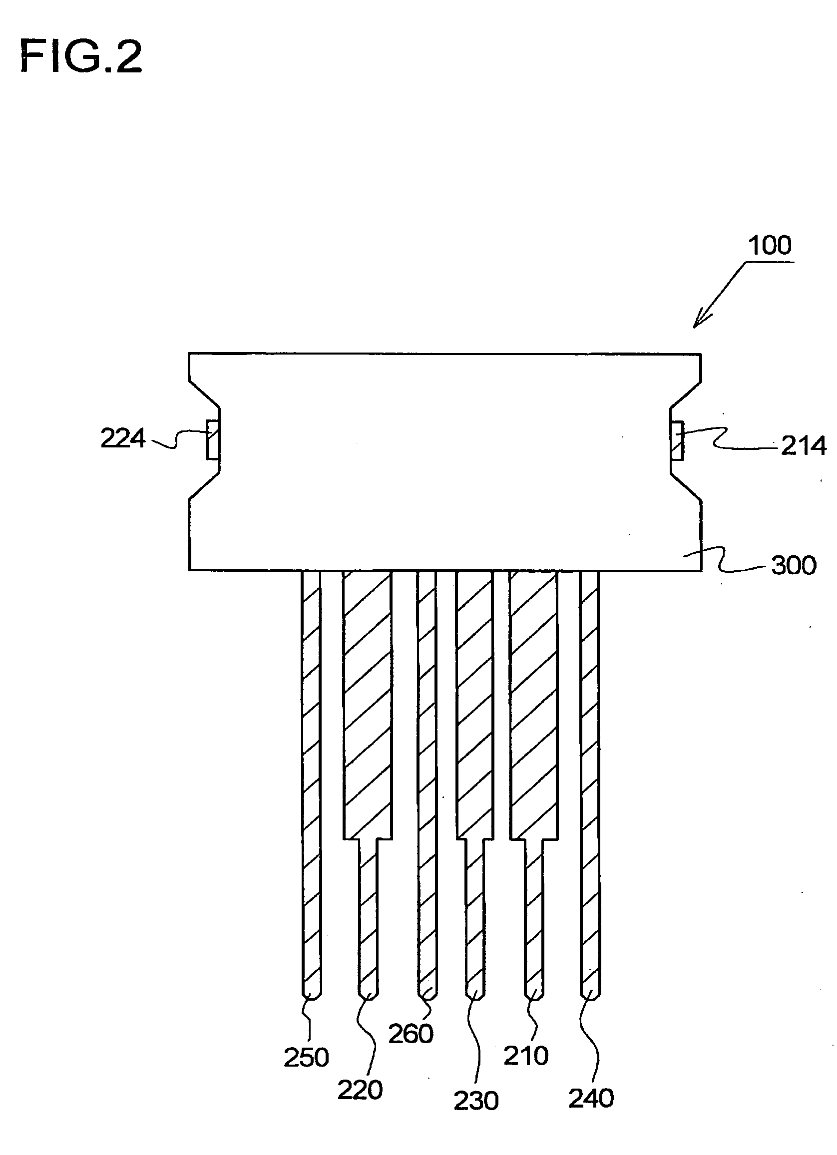
[0079] A light emitting apparatus according to a first embodiment is described with reference to drawings. FIG. 1 is a schematic front view showing the light emitting apparatus according to the first embodiment. FIG. 2 is a schematic back view showing the light emitting apparatus according to the first embodiment. FIG. 3 is a schematic left side view showing the light emitting apparatus according to the first embodiment. FIG. 4 is a schematic view showing a first lead terminal according to the first embodiment. FIG. 5 is a schematic view showing a lead frame according to the first embodiment.

[0080] A light emitting apparatus 100 according to the first embodiment comprises a first GaN group light emitting element 110 having a first light emission peak wavelength; a second GaN group light emitting element 120 having a second light emission peak wavelength longer than the first light emission peak wavelength; a third light emitting element 130 having a thir...

second embodiment

[0120] A light emitting apparatus according to a second embodiment is described with reference to drawings. FIG. 7 is a schematic front view showing the light emitting apparatus according to the second embodiment. FIG. 8 is a schematic right side view showing the light emitting apparatus according to the second embodiment. The description of the substantially same structure as the light emitting apparatus according to first embodiment is omitted.

[0121] The light emitting apparatus 400 according to the second embodiment includes a first lead terminal 510, a second lead terminal 520, a third lead terminal 530, and a fourth lead terminal 540. The fourth lead terminal 540 serves as an integral lead terminal of the fourth lead terminal 210 to the sixth lead terminal 260 in the first embodiment. First, second and third light-emitting elements 410, 420 and 430 are mounted on the first, second and third lead terminals 510, 520 and 530, respectively. The first, second and third light-emitti...

third embodiment

[0123] A light emitting apparatus according to a third embodiment is described with reference to drawings. FIG. 9 is a schematic front view showing the light emitting apparatus according to the third embodiment. The description of the substantially same structure as the light emitting apparatus according to first embodiment is omitted.

[0124] Third portions of first to sixth lead terminals 810 to 860 are formed so as to provide an anchor effect. The reason is to prevent the lead terminals from dropping off from a securing member 900. For example, the lead terminal can have the variation of the width, a bent shape, or asperities. In addition, first portions of the first to sixth lead terminals 810 to 860 are formed at a prescribed angle. Accordingly, it is possible to prevent the lead terminals from dropping off from the securing member 900.

[0125] The light emitting apparatus 700, and so o, can further include one or more lead terminals, and a light emitting element can be mounted t...


PUM


Abstract

A first GaN group light emitting element that emits blue light, a second GaN group light emitting element that emits green light, and a third light emitting element that emits red light are provided on a first lead terminal, a second lead terminal, and a third lead terminal, respectively. These lead terminals are secured by a securing member. A second portion in the first lead terminal and a second portion in the second lead terminal are wider than a second portion in the third lead electrode. The second portion of the third lead terminal is wider than parts corresponding to second portions of the fourth lead terminal to the sixth lead terminal.

Description

BACKGROUND OF THE INVENTION [0001] 1. Field of the Invention [0002] The present invention relates to a light emitting apparatus used in an image reader, backlight for liquid crystal, and so on. More particularly, the present invention relates to a light emitting apparatus used in a facsimile, a copier, a scanner, and so on. [0003] 2. Description of the Related Art [0004] A light source apparatus for a conventional scanner, and so on, shown in FIG. 15 is known (for example, see Japanese Laid-Open Publication Kokai No. HEI 11-330557 (FIG. 3)). This light emitting apparatus includes a first lead frame 3210, a second lead frame 3220, a third lead frame 3230, a fourth lead frame 3240, and a resin member 4300 that secures these lead frames. The first lead frame 3210 includes a first portion 3211 that is electrically connected to an external terminal, a second portion 3212 that is exposed from the resin member 4300, and a third portion 3213 that is provided with a first light emitting elem...

Claims


Application Information

Patent Timeline
IPC IPC(8): H01L33/00H01L33/06H01L33/32H01L33/50H01L33/56H01L33/62H01L33/64
CPCH01L25/0753H01L33/62H01L2224/45144H01L2924/00H01L2224/48247H01L2224/48091H01L2924/00014H01L2224/48257H01L2224/49113
Inventor SUMITANI, NAOFUMI
Owner NICHIA CORP
Why Eureka
Try Eureka