Controlling inrush current

a technology of inrush current and control voltage, applied in the field of inrush current, can solve the problems of high inrush current damage to components, trip circuit breakers, and other undesirable effects

Inactive Publication Date: 2006-06-22
HEWLETT PACKARD DEV CO LP
View PDF25 Cites 59 Cited by
  • Summary
  • Abstract
  • Description
  • Claims
  • Application Information

AI Technical Summary

Problems solved by technology

If left uncontrolled, a high inrush current can damage components, trip circuit breakers, and have other undesirable effects.

Method used


Image

  • Controlling inrush current
  • Controlling inrush current
  • Controlling inrush current

Examples


Embodiment Construction

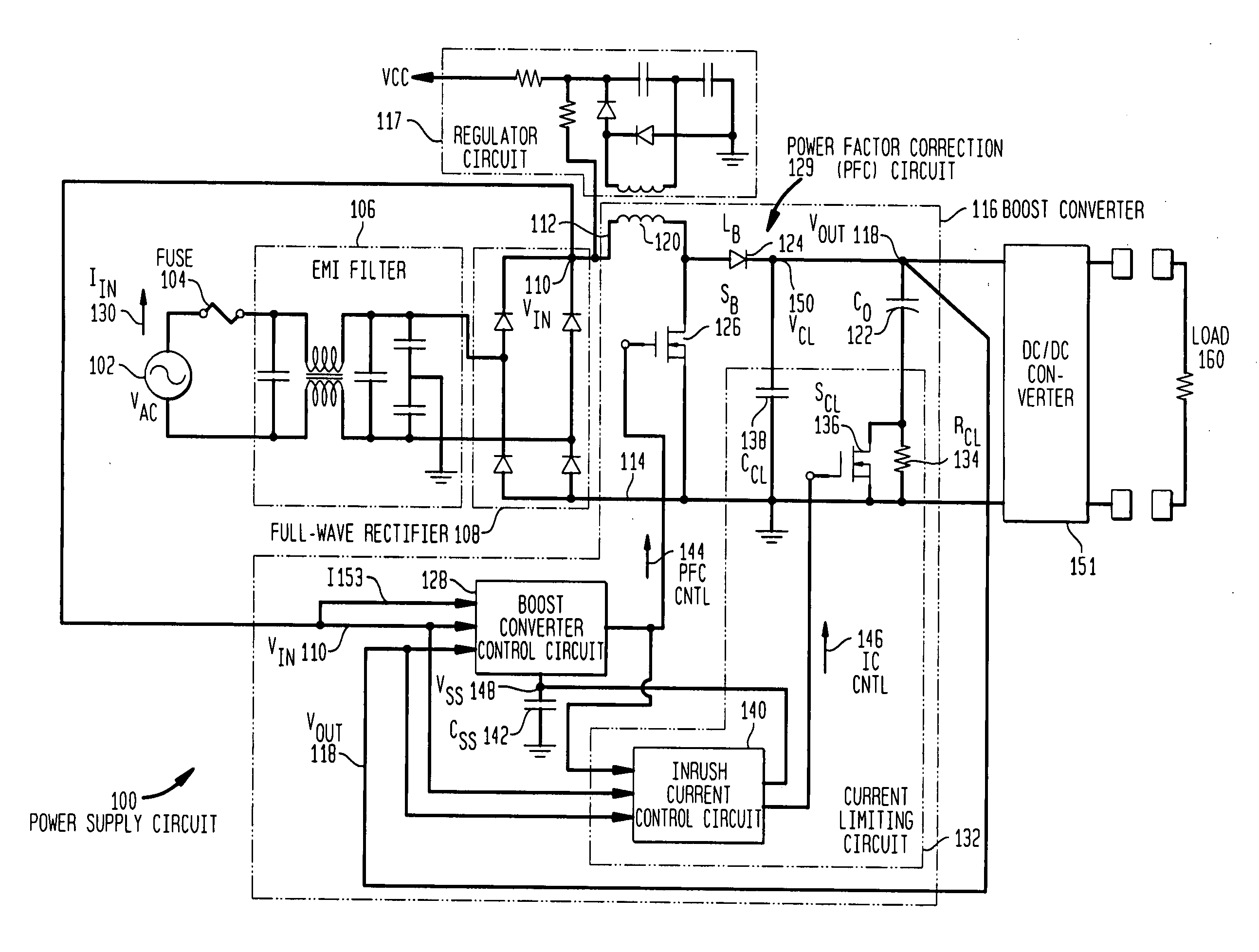
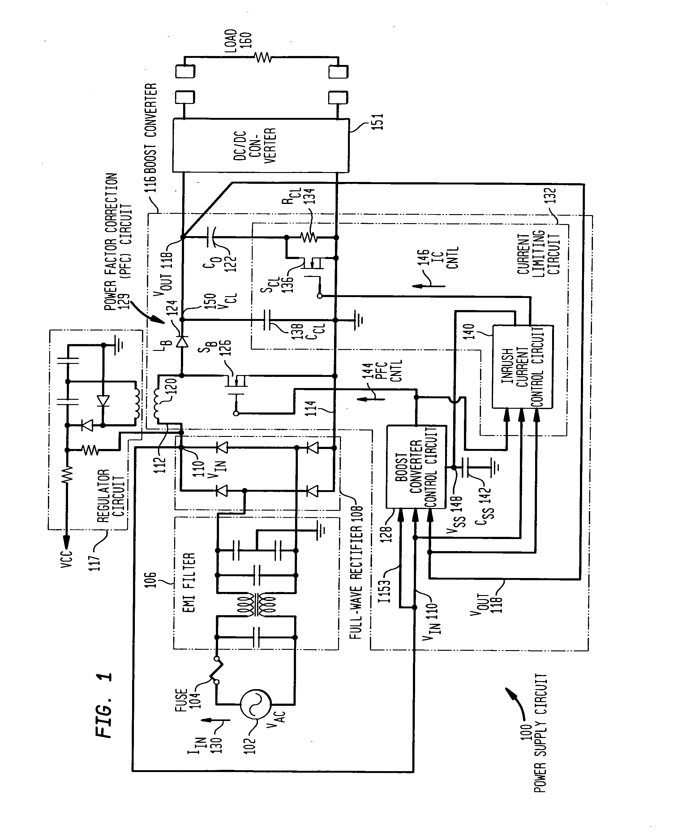
[0024]FIG. 1 is simplified schematic diagram of a power supply circuit 100 in accordance with one embodiment of the present invention. An alternating current (AC) voltage VAC 102 such as a utility line voltage is received through a fuse 104. AC line voltage 102 is filtered through an electromagnetic interference (EMI) filter 106 and provided to a full-wave rectifier 108. Full-wave rectifier 108 rectifies AC line voltage 102 to provide a rectified input voltage VIN 110 on conductor 112 with respect to a reference or ground conductor 114. In the exemplary embodiment shown in FIG. 1, rectifier 108 is a diode rectifier, although in alternative embodiments other types of rectifiers may be used. EMI filter 106 and rectifier 108 are collectively referred to herein as a phase control rectifying circuit. The structure and operation of EMI filter 106 and rectifier 108 are well-known to those of ordinary skill in the art and, therefore, are not described further herein.

[0025] Power supply cir...


PUM


Abstract

A control circuit and method for controlling a power factor correction circuit comprising: an inductor having an input terminal to receive an input voltage and an output terminal series connected to an anode of a diode; a first capacitor connected between a cathode of said diode and ground; a first switch connected between an anode of said diode and ground; a series arrangement of a second capacitor and a parallel arrangement of a resistor and a second switch series connected with said second capacitor. The control circuit is operable to generate synchronous first and second switch control signals to respectively control said first and second switches, wherein during inrush current conditions when said input voltage drops-in after an interruption, said control circuit is operable to cause said first and second switches to be synchronously switched at increasing duty cycles. The method comprises charging a first capacitor from an input voltage source; isolating the first capacitor from the input voltage source; transferring a portion of charge stored in said first capacitor to a second capacitor while said input voltage source is isolated from said first capacitor and from said second capacitor; and repeatedly said charging, isolating, and transferring until a voltage is formed on said second capacitor that is approximately equal to said input voltage source.

Description

BACKGROUND [0001] 1. Field of the Invention [0002] The present invention relates generally to inrush current and, more particularly, to controlling inrush current. [0003] 2. Related Art [0004] Line-operated power supplies that are used to supply power to computers, servers and other systems normally receive power from single-phase alternating current (AC) utility voltage (110 V RMS in the United States and 220 V RMS in Europe and Asia). Typical power supplies have at their front-end a power factor correction (PFC) circuit to insure the input power factor is near unity. Unity power factor requires the instantaneous input current to be proportional to the instantaneous input voltage. When this relationship is attained, the PFC circuit appears as a resistive load to the AC power source, while generating a regulated DC voltage for load line variations from, for example, 90VAC RMS to 264VAC RMS. [0005] When a power supply is connected to the AC power source, a short-duration, high-amplit...

Claims


Application Information

Patent Timeline
Patent Type & Authority Applications(United States)
IPC IPC(8): G05F1/656G05F1/10
CPCH02M1/4225Y02B70/126Y02B70/10H02H9/001
Inventor PRASAD, ATLURI R.NGUYEN, HAI N.
Owner HEWLETT PACKARD DEV CO LP
Why Eureka
Try Eureka