Near field location system and method

a near field and location technology, applied in the direction of navigation instruments, polarised antenna unit combinations, instruments, etc., can solve the problems of serious affecting the performance of the signal strength ranging scheme, confounding efforts, and wildly inaccurate typical signal strength ranging schemes, etc., to achieve the effect of reducing interference, facilitating portability and facilitating operation

Inactive Publication Date: 2006-06-22
Q TRACK CORP
View PDF99 Cites 67 Cited by
  • Summary
  • Abstract
  • Description
  • Claims
  • Application Information

AI Technical Summary

Benefits of technology

[0011] Accordingly, one object of the present invention is to provide location capability by utilizing space efficient antennas, antennas that may be easily portabl

Problems solved by technology

These efforts are confounded by the impact of typical multi-path heavy environments which act to constructively and destructively combine signals in such a fashion as to render typical signal strength ranging schemes wildly inaccurate.
Furthermore, existing amplitude or signal strength pos

Method used


Image

  • Near field location system and method
  • Near field location system and method
  • Near field location system and method

Examples


Embodiment Construction

[0049] The present invention is directed to a near field location system and method. The present invention will now be described more fully in detail with reference to the accompanying drawings, in which the preferred embodiments of the invention are shown. This invention should not, however, be construed as limited to the embodiments set forth herein; rather, they are provided so that this disclosure will be thorough and complete and will fully convey the scope of the invention to those skilled in the art. Like numbers refer to like elements throughout.

Near Field Propagation

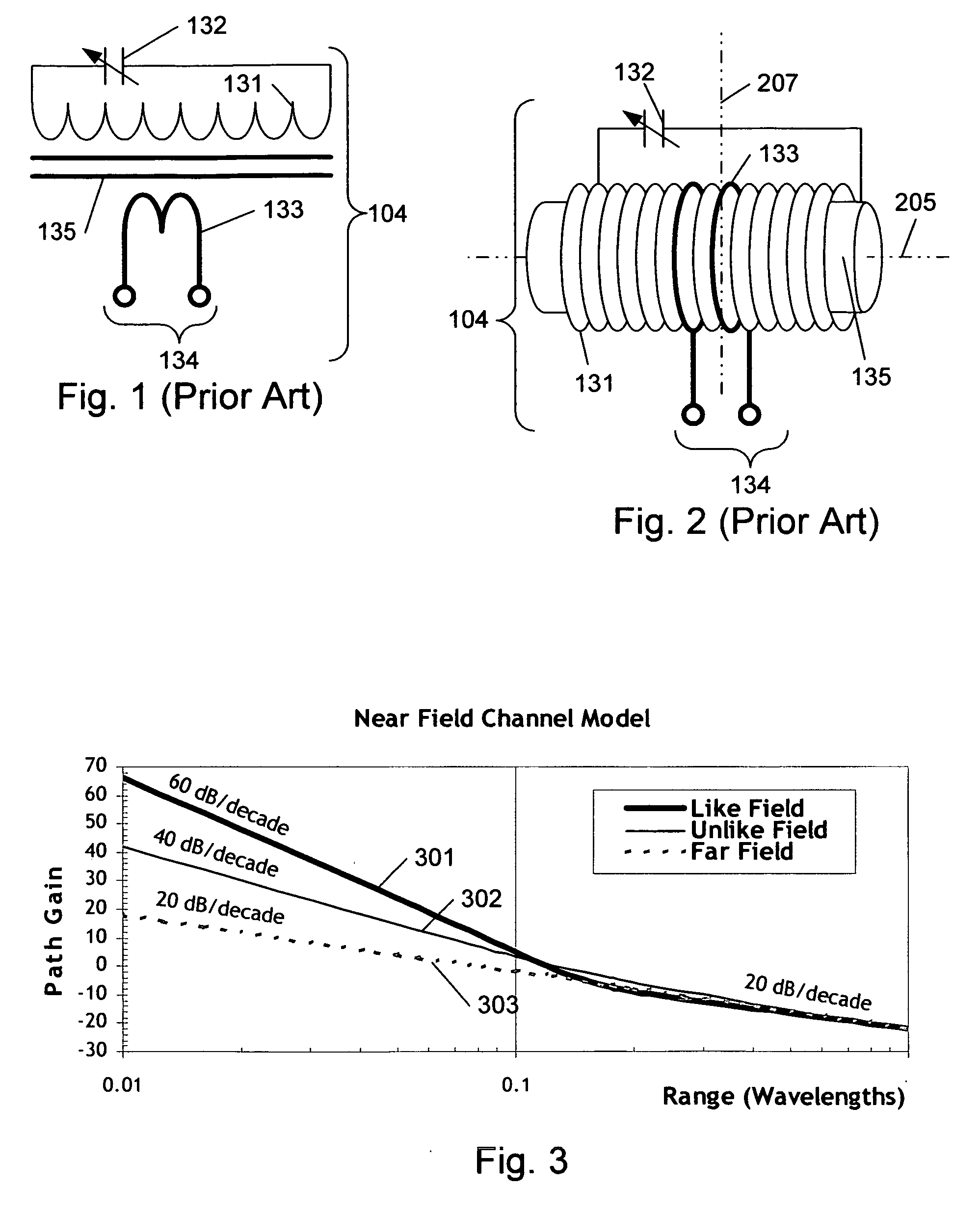
[0050] A near field location system may rely on certain properties of near field electromagnetic signals. FIG. 3A is plot of path gain versus range in free space for electric and magnetic signals from a small electric transmit antenna as electric and magnetic signals transition from the near field to the far field. At a range approximately equal to about one sixth of a wavelength (λ / 2π), electromagnetic signa...


PUM


Abstract

Near field signal properties are used to determine a location by utilizing two magnetic antennas arranged so that the null axes are perpendicular and lie in a plane of interest, such as the horizontal plane. The two antennas may be used as transmitting antennas or receiving antennas. The antennas may be driven so as to produce an equivalent of an omnidirectional pattern in the plane of interest by driving the antennas in an orthogonal manner. The orthogonal drive may be time orthogonal or phase orthogonal. A location is determined based on near field response which may include propagation properties, which may include amplitude, phase, relative amplitude, or phase, or other properties. In one embodiment, multiple transmitters are utilized to determine the location of a single receiver. In another embodiment, multiple receivers are utilized to determine the location of a single transmitter. A space efficient magnetic antenna is disclosed.

Description

RELATED APPLICATIONS [0001] This application claims the benefit under 35 USC 119(e) of provisional application Ser. No. 60 / 637,779, Titled: “Near Field Amplitude Positioning System and Method,” filed Dec. 21, 2004 by Schantz et al., which is incorporated herein by reference in its entirety. [0002] Near field electromagnetic ranging was first fully described in applicant's “System and Method for Near-Field Electromagnetic Ranging” (application Ser. No. 10 / 355,612, filed Jan. 31, 2003, now U.S. Pat. No. 6,963,301, issued Nov. 8, 2005), which is incorporated herein by reference in its entirety. [0003] Further details on electromagnetic ranging and positioning are disclosed in U.S. patent application Ser. No. 10 / 958,165 titled “Near Field Electromagnetic Positioning System and Method,” filed Oct. 4, 2004 by Schantz et al. and U.S. patent application Ser. No. 11 / 215,699, titled “Low Frequency Asset Tag Tracking System and Method,” filed Aug. 30, 2005 by Schantz et al. All of the above li...

Claims


Application Information

Patent Timeline
IPC IPC(8): G01S13/08G01S19/25G01S5/02G01S5/14
CPCG01C21/206G01S5/0252G01S5/14H01Q1/273H01Q1/276H01Q7/08H01Q21/24H04B5/0075
Inventor SCHANTZ, HANS GREGORYDEPIERRE, ROBERT EDWARDWOLENEC, GLENNSIWIAK, KAZIMIERZGABIG, JEROME SYLVESTER
Owner Q TRACK CORP
Why Eureka
Try Eureka