Illuminating device and projection type image display unit

a technology of projection type and image display unit, which is applied in the direction of projectors, color television details, instruments, etc., can solve the problems of irradiation surface to glare, gaussian distribution of light-emitting intensity, and inability to obtain a practical illuminating device using light-emitting diodes, etc., to achieve the effect of reducing the amount of ligh

Inactive Publication Date: 2006-06-22
SANYO ELECTRIC CO LTD
View PDF7 Cites 82 Cited by
  • Summary
  • Abstract
  • Description
  • Claims
  • Application Information

AI Technical Summary

Benefits of technology

[0025] Moreover, an illuminating device of the present invention is characterized in that a plurality of solid light-emitting elements are three-dimensionally arranged in a mirror surface cylinder, one surface of which is a light-exit surface and inner sides of other surfaces of which are reflective surfaces, and light emitted from the solid light-emitting elements is integrated by the reflective surfaces and given off from the light-exit surface. With the above-described configuration, a plurality of solid light-emitting elements are three-dimensionally arranged, so that it is possible to increase the light amount. In addition, the light emitted from each solid light-emitting element is reflected in the mirror surface cylinder, integrated, and given off from the light-exit surface, so that it is possible to prevent bright and dark portions corresponding to an arrangement of the solid light-emitting elements from being generated on the object to be illuminated. It is preferable that the mirror surface cylinder is in a shape of a rectangular tubular body. In addition, it is preferable that an aspect ratio of the light-exit surface coincides or approximately coincides with an aspect ratio of an object to be illuminated. This makes it possible that the light emitted from the solid light-emitting elements is guided onto an entire surface of the object to be illuminated without being wasted. As a result, the utilization efficiency of the emitted light is improved. It is prefera

Problems solved by technology

However, in reality, a practical illuminating device using the light-emitting diode has not been obtained.
However, in a case of using a plurality of laser diodes which emit light of the same wavelength, there is a disadvantage that a speckle noise (a high-contrast speckle pattern generated in a space when a rough surface or a heterogeneous medium is irradiat

Method used


Image

  • Illuminating device and projection type image display unit
  • Illuminating device and projection type image display unit
  • Illuminating device and projection type image display unit

Examples


embodiment 1

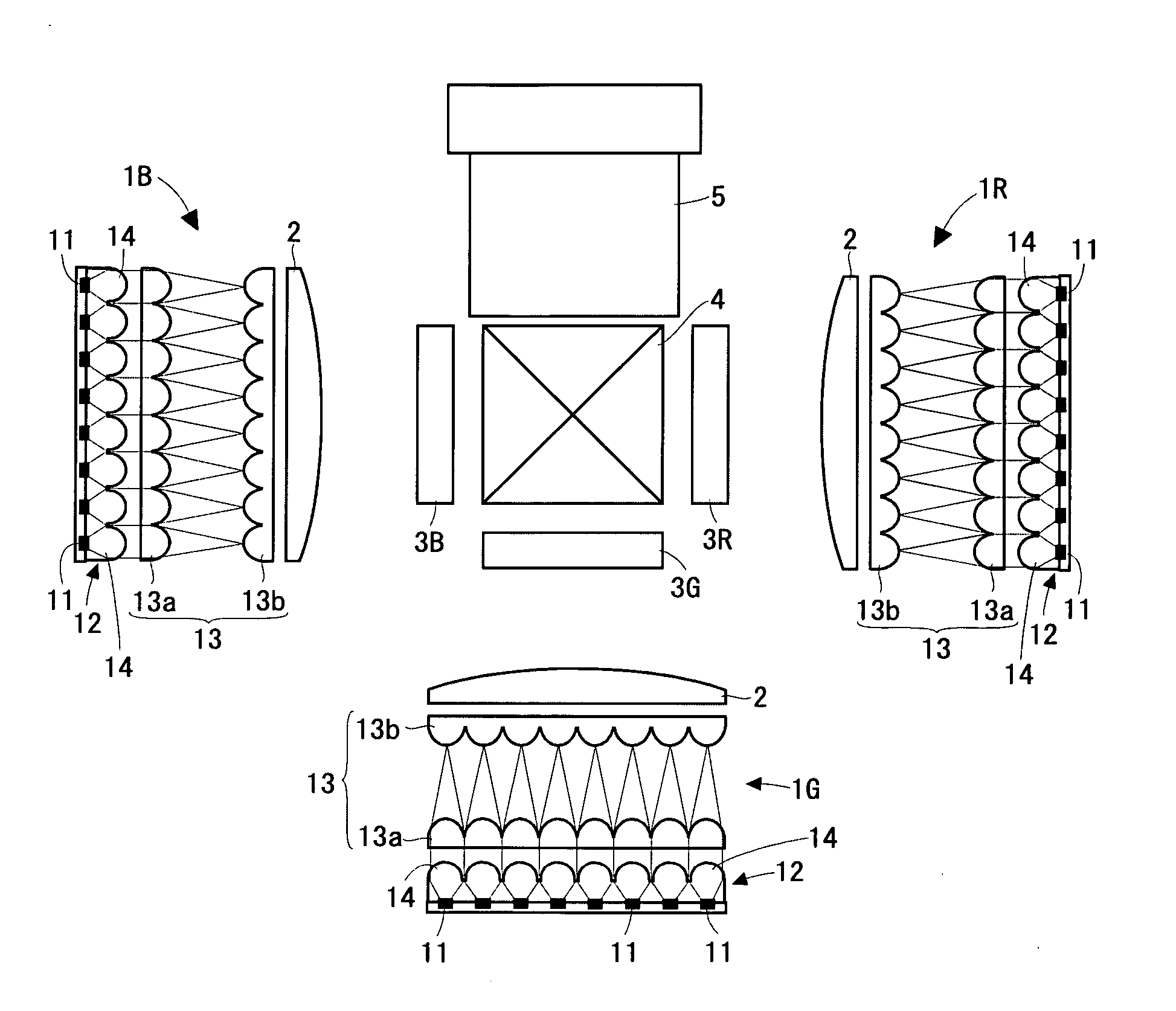
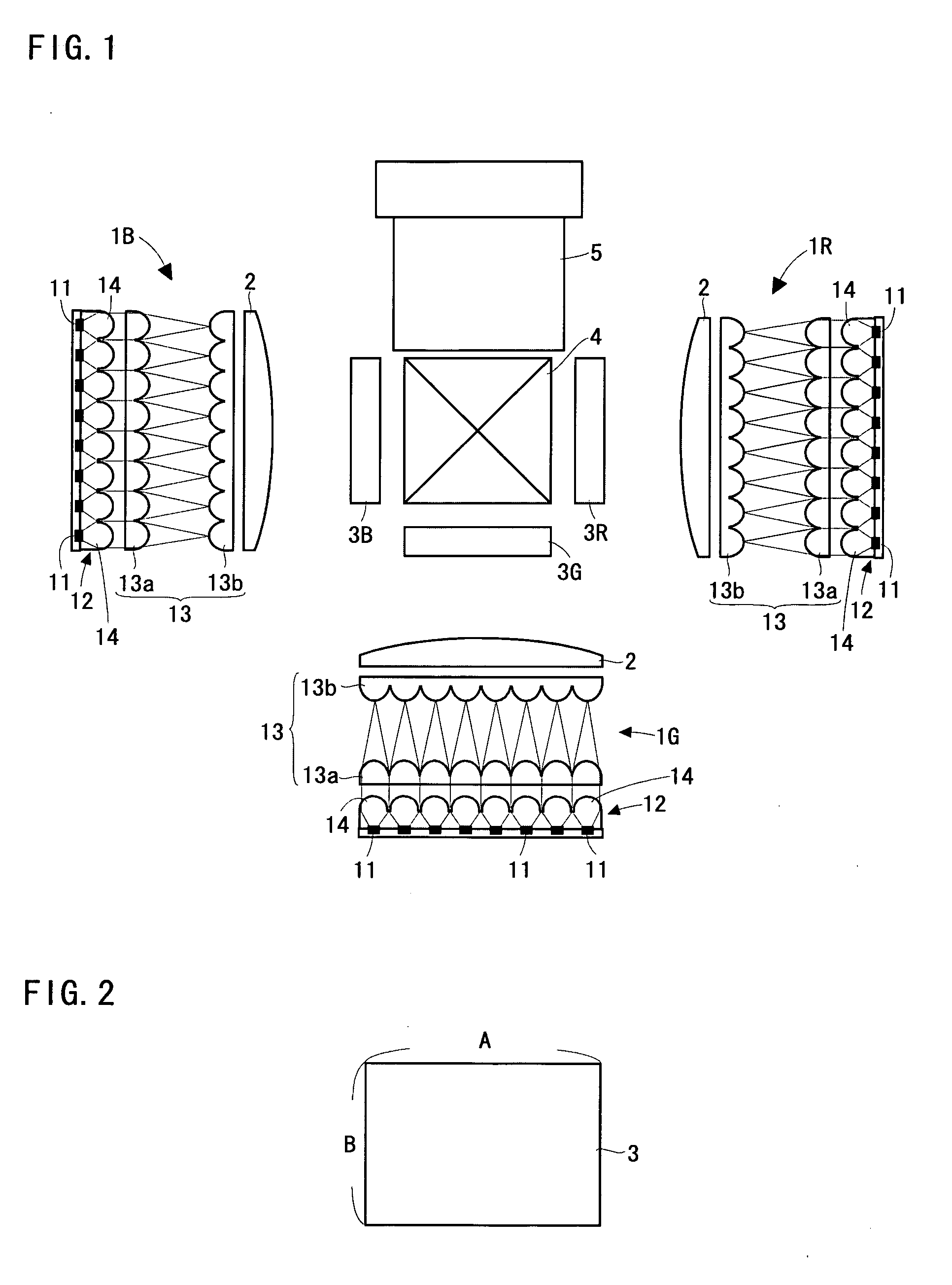
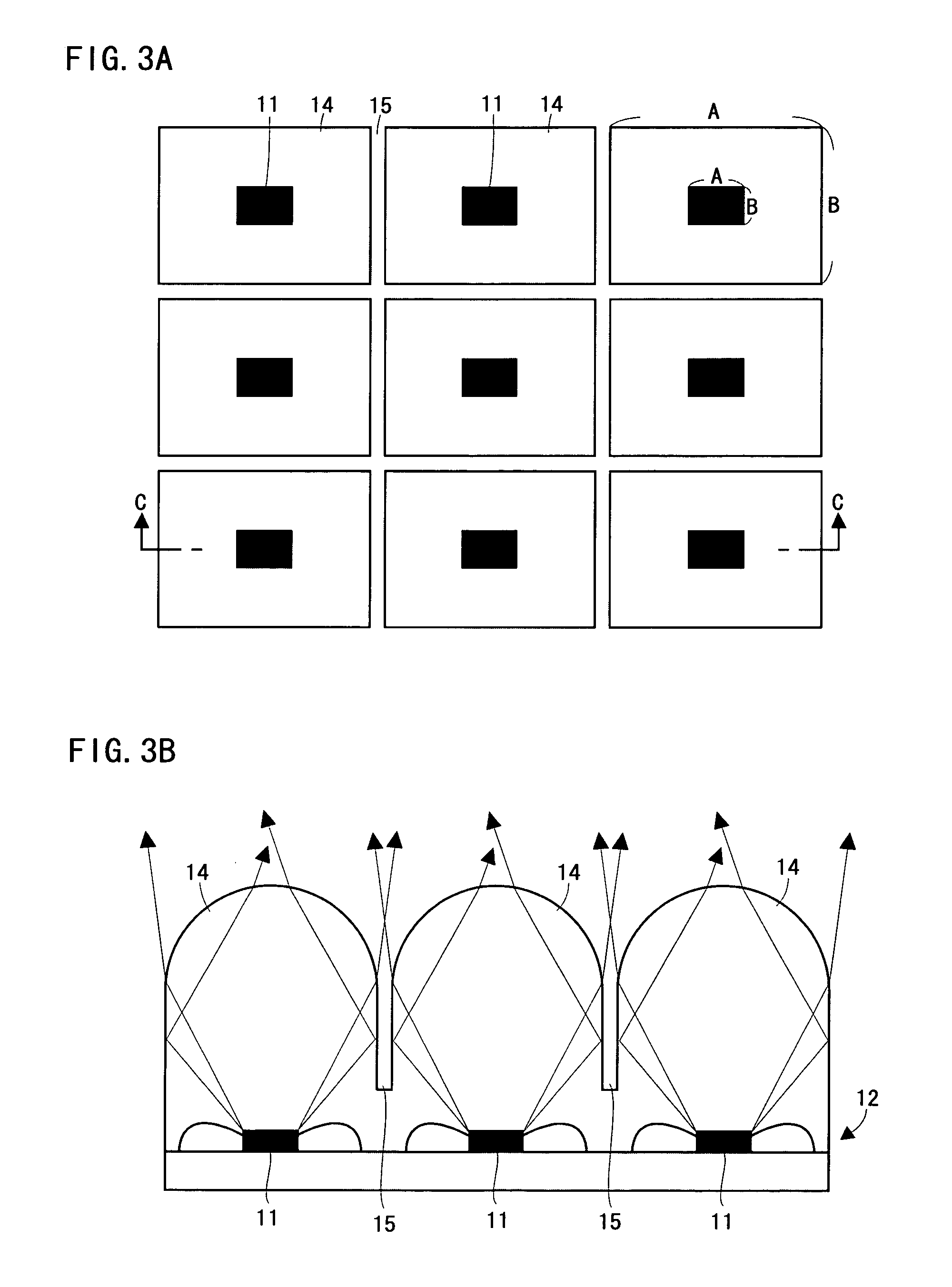
[0061] Hereinafter, an illuminating device and a projection type video display will be described on the basis of FIGS. 1 to 8, and FIG. 26.

[0062]FIG. 1 is a diagram showing an optical system of a three-panel projection type video display. The projection type video display comprises three illuminating devices 1R, 1G, and 1B. (Hereinafter, a numeral “1” is used when generally referring to the illuminating device). The illuminating device 1R emits light in red, the illuminating device 1G emits light in green, and the illuminating device 1B emits light in blue. The light emitted from each illuminating device 1 is guided to transmission type liquid crystal display panels 3R, 3G, and 3B for respective colors (Hereinafter, a numeral “3” is used when generally referring to the crystal display panel) by a convex lens 2. Each liquid crystal display panel 3 is formed of being provided with an incidence-side polarizer, a panel portion formed by sealing a liquid crystal between a pair of glass ...

embodiment 2

[0075] Hereinafter, an illuminating device and a projection type video display according to the embodiment 2 of the present invention will be described on the basis of FIGS. 9 to 13.

[0076]FIG. 9 is a diagram showing an optical system of a three-panel projection type video display. This projection type video display is provided with three illuminating devices 101R, 101G, and 101B (Hereinafter, a numeral “101” is used when generally referring to the illuminating device). The illuminating device 101R emits light in red, the illuminating device 101G emits light in green, and the illuminating device 101B emits light in blue. The light emitted from each illuminating device 101 is guided to liquid crystal display panels 103R, 103G, and 103B for respective colors (Hereinafter, numeral “103” is used when showing not specifying each liquid crystal display panel) by a condenser lens 102. Each liquid crystal display panel 103 is formed of being provided with an incidence-side polarizer, a pane...

embodiment 3

[0087] Hereinafter, an illuminating device and a projection type video display according to the embodiment 3 of the present invention will be described on the basis of FIGS. 14 to 21.

[0088]FIG. 14 is a diagram showing an optical system of a three-panel projection type video display. This projection type video display is provided with three illuminating devices 201R, 201G, and 201B (Hereinafter, a numeral “201” is used generally referring to the illuminating device). The illuminating device 201R emits light in red, the illuminating device 201G emits light in green, and the illuminating device 201B emits light in blue. The light emitted from each illuminating device 201 is guided to liquid crystal display panels 203R, 203G, and 203B for respective colors (Hereinafter, a numeral “203” is used when generally referring to the liquid crystal display panel) by a condenser lens 202. Each liquid crystal display panel 203 is formed of being provided with an incidence-side polarizer, a panel ...


PUM


Abstract

An illuminating device (1) is formed of a light source (12) in which LED chips (11) are arranged in an array shape and lens cells (14) are arranged on a light-emission side of each of the LED chips (11), and a pair of fly's eye lenses (13) that integrates and guides to a liquid crystal panel (3) the light emitted from each of the LED chips (11) and collimated by the lens cells (14). The LED chip (11) and the lens cell (14) are formed in a square shape, and an aspect ratio thereof corresponds to that of the liquid crystal display panel (3). In addition, the lens cells (14) are arranged separately from one another in such a manner to have wall surfaces (air gaps), and the wall surfaces serve as reflective surfaces.

Description

TECHNICAL FIELD [0001] The present invention relates to an illuminating device and a projection type video display. PRIOR ART [0002] Generally, an illuminating device used for a liquid crystal projector, and others is formed of a lamp such as an ultra-high pressure mercury lamp, a metal halide lamp, a xenon lamp, and etc., and a parabolic reflector that collimates irradiating light. In addition, in such the illuminating device, in order to reduce a non-uniformity of a light amount on an irradiating surface, there is an integrating function by a pair of fly's eye lenses (referred to as a function for superimposing and converging plural illuminating areas of predetermined shape formed by sampling within a plane surface by an optical device on an object to be illuminated). Furthermore, in recent years, from the viewpoint of reduction in size and weight, it is attempted to use a light-emitting diode (LED) as the light source (see Japanese Patent Application Laying-open No. H10-186507). ...

Claims


Application Information

Patent Timeline
IPC IPC(8): G03B21/14G02B27/14
CPCG02B27/102G02B27/1046G02B27/126G02B27/149H04N9/315G02B5/02G02B27/10
Inventor TERADA, FUSAOTORAZAWA, KENJIFUNAZOU, YASUOTSUCHIYA, YOICHIHIBINO, KATSUTOSHIKANAYAMA, HIDEYUKIYOSHII, SHOUICHIKUROSAKA, YOSHITAKA
Owner SANYO ELECTRIC CO LTD
Why Eureka
Try Eureka