
Method for making an optical system with coated optical components and optical system made by the method

a technology of optical components and optical systems, applied in the direction of photomechanical treatment, instruments, polarising elements, etc., can solve the problems of non-uniform intensity distribution, problem area may occur, non-uniform intensity over field and pupil

Inactive Publication Date: 2006-06-22
CARL ZEISS SMT GMBH
View PDF1 Cites 0 Cited by
  • Summary
  • Abstract
  • Description
  • Claims
  • Application Information

AI Technical Summary

Benefits of technology

[0014] One object of the invention is to provide a method for making an optical system which makes it possible, in a simple and rapid manner, to optimize the optical system for an envisaged imaging quality with inclusion of the optical effect of interference layer systems on optical components.
[0020] In preferred variants of the optimization strategy according to the invention, a direct program-technical combination of suitable layer variation algorithms with an assessment of the imaging quality of the entire optical system including the interference layer system to be optimized is provided, which can be carried out rapidly with tenable computational complexity. For this purpose, the step of determining the imaging quality of the optical system comprises determining Jones matrices, which permit in particular a fast and reliable assessment of the total transmission of a system even taking account of the use of polarized radiation. This is explained in more detail below using the example of a system in which the interference layer system to be optimized is a polarization-selective beam splitter layer.
[0053] The invention also relates to an optical system comprising an optical axis and at least one physical beam splitter with a polarization-selective beam splitter layer which is tilted by a layer tilting angle about a layer tilting axis relative to the optical axis and can be loaded with radiation from a total angle of incidence range which, in particular, is a function of the layer tilting angle, the orientation of the layer tilting axis and the numerical aperture of the projection objective. The beam splitter layer has reflectance RsBS for s-polarized light and a transmittance TpBS for p-polarized light, in which case profiles of RsBS and TpBS dependent on angle of incidence define a transmission product RsBS·TpBS for corresponding angles of incidence. The beam splitter layer is loaded in a plane parallel to the layer tilting axis in a first angle of incidence range and in a plane perpendicular to the layer tilting axis in a second angle of incidence range, which is larger than the first angle of incidence range. The transmission product is essentially constant for angles of incidence from the first angle of incidence range, while the transmission product for angles of incidence of the second angle of incidence range which lie outside the first angle of incidence range deviates significantly from a mean value of the transmission product of the first angle of incidence range. The deviation is preferably such that the transmission product for angles of incidence outside the first angle of incidence range is substantially lower than that for angles of incidence within the first angle of incidence range. In this way, it is possible to selectively apodize rays from the extreme value ranges of the second, larger angle of incidence range in order, in this way, to obtain a uniform total transmission despite an overall great variation of the transmission product over the total angle of incidence range of the interference layer system for the total system.

Problems solved by technology

Especially in systems that operate with polarized light, reflectivity or transmission properties of interference layer systems that are dependent on the angle of incidence may lead to nonuniformities of the intensity over field and pupil.
This problem area may occur in the case of purely refractive (dioptric) imaging systems, in particular in high-aperture systems having many lenses coated with antireflection layers.
Finally, material defects, e.g. scattering centers or striations in transparent components, may also lead to nonuniformities of the intensity distribution.
Although the known procedures for layer optimization to given target functions have proved worthwhile in many applications, fundamental problems remain.
Firstly, it is often difficult to define suitable target profiles.
Even if optimum target profiles for the polarization-dependent reflectances and transmittances or functions of these values are found, it is still not guaranteed that a layer design that can be realized can approximate such a target function sufficiently well.
As a result, the choice of the optimum target functions is made more difficult.

Method used


Image

  • Method for making an optical system with coated optical components and optical system made by the method
  • Method for making an optical system with coated optical components and optical system made by the method
  • Method for making an optical system with coated optical components and optical system made by the method

Examples


Embodiment Construction

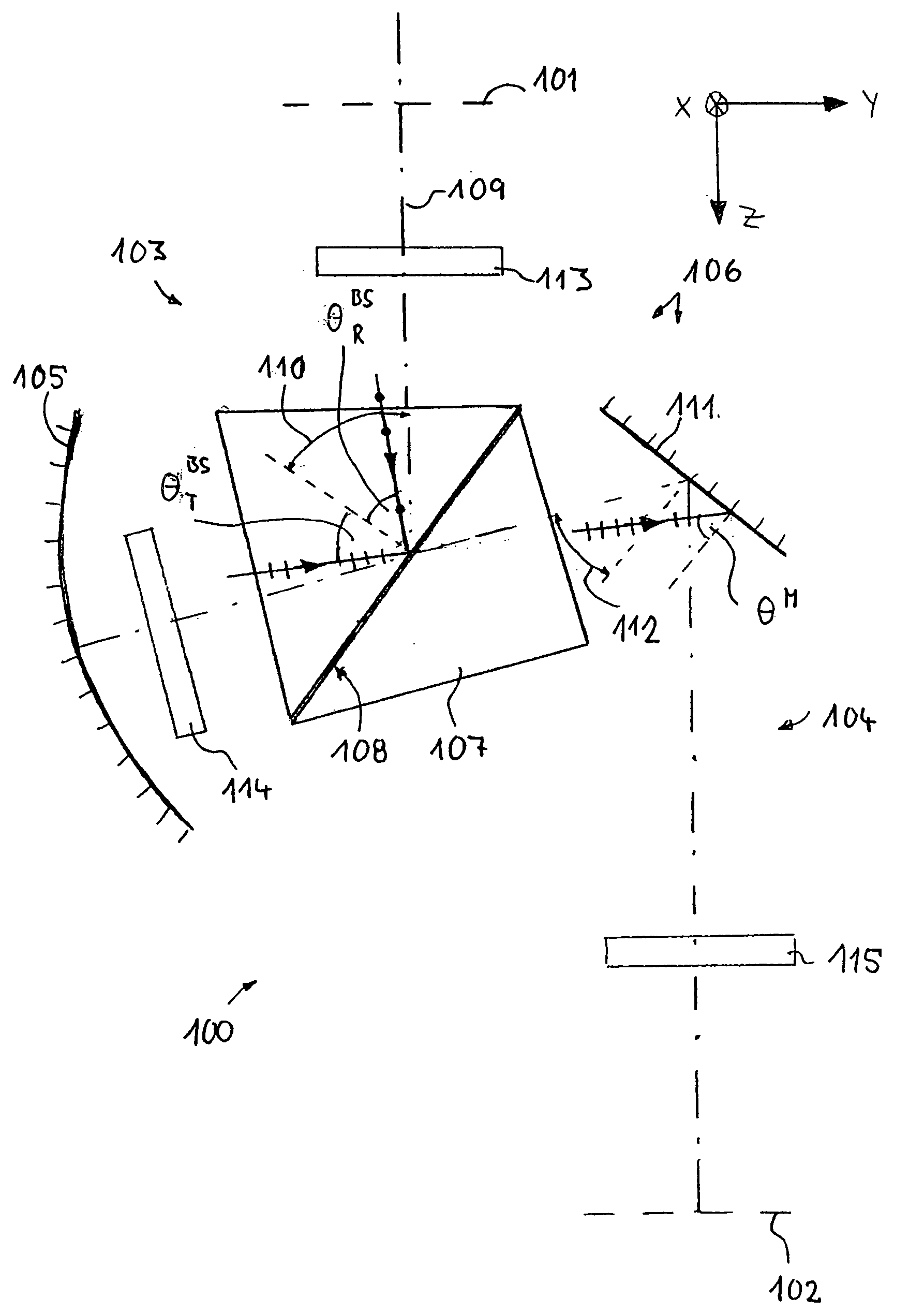
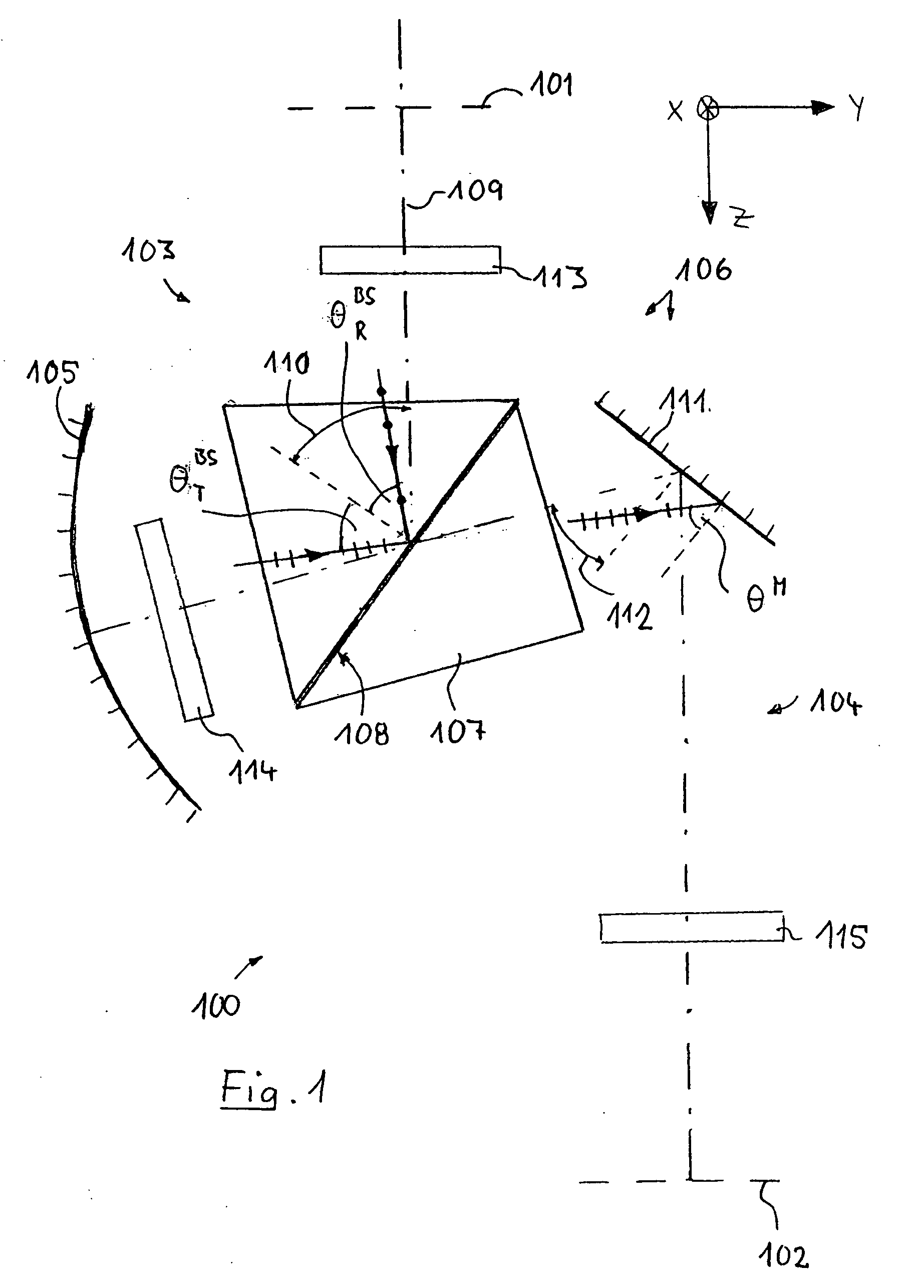
[0066]FIG. 1 schematically shows the construction of an embodiment of a catadioptric reduction objective 100 according to the invention. It serves, at an operating wavelength in the deep ultraviolet range of approximately 157 nm, for imaging a pattern of a reticle or the like arranged in the object plane 101 into the image plane 102 on a reduced scale, for example with the ratio 4:1, with exactly one real intermediate image being generated. The projection objective has, between the object plane and the image plane, a catadioptric objective part 103 and behind that a purely dioptric objective part 104. The lens of the objective parts which serve for imaging are not illustrated for reasons of clarity.

[0067] The catadioptric objective part 103 comprises a concave mirror 105 and a beam deflection device 106. The beam deflection device comprises a physical beam splitter 107 with a polarization-selective beam splitter layer 108, which is formed by a multilayer interference layer system m...


PUM


Abstract

In a method for making an optical system for imaging a radiation distribution from an input surface of the optical system into an output surface of the optical system, the optical system has a multiplicity of optical components which determine an imaging quality of the optical system, which are arranged along an optical axis of the optical system and comprise at least one optical component which has a substrate with a substrate surface which is provided for carrying an interference layer system having a layer construction that determines the optical properties of the optical component covered with the interference layer system. The method includes: predefining an optimization target for at least one imaging quality parameter that represents the imaging quality of the system; determining the imaging quality of the optical system while taking account of the layer construction of the interference layer system; and varying the layer construction for approximating the imaging quality parameter to the optimization target. In accordance with the method, the determination of the optimum layer construction is coupled directly with an assessment and of the imaging quality of the total system including the interference layer system to be optimized.

Description

[0001] This application claims the benefit of U.S. Provisional Application No. 60 / 627,906, filed Nov. 16, 2004.BACKGROUND OF THE INVENTION [0002] 1. Field of the Invention [0003] The invention relates to a method for making an optical system for imaging a radiation distribution from an input surface of the optical system into an output surface of the optical system, and to an optical system which can be made or is made with the aid of the method. A preferred field of application for the invention is making optical imaging systems for microlithographic projection exposure apparatuses. The input surface and the output surface may be optically conjugate field planes, for example the object plane and the image plane of a projection objective. [0004] 2. Description of the Related Prior Art [0005] Projection exposure apparatuses for microlithography are used for fabricating semiconductor components and other finely patterned devices. They serve for projecting patterns from photomasks or r...

Claims


Application Information

Patent Timeline
Patent Type & Authority Applications(United States)
IPC IPC(8): G02B27/28
CPCG02B27/0012G02B27/283G03F7/705G03F7/70958
Inventor ZACZEK, CHRISTOPHMUELDERS, THOMASGRUNER, TORALF
Owner CARL ZEISS SMT GMBH
Learn More