Apparatus for administering light stimulation

a technology of light stimulation and apparatus, applied in light therapy, radiation therapy, sleep inducing/ending devices, etc., can solve the problems of large light boxes, adversely affecting the sleep and alertness of sufferers, and requiring domestic high-voltage power sources

Inactive Publication Date: 2006-06-22
RE TIME PTY LTD
View PDF17 Cites 43 Cited by
  • Summary
  • Abstract
  • Description
  • Claims
  • Application Information

AI Technical Summary

Benefits of technology

[0013] The terminals may be connected to the power supply using a permanent joint (such as a solder joint) or using a make-break type electrical connector. Advantageously, the inclusion of the terminals on conductive ear stems provides a neat arrangement of a relatively simple design which avoids the need to include additional electrical wiring on the frame itself.
[0038] Preferably, the pairs of light emitting diodes are spaced apart such that the distance between the midpoints of the viewing zones is substantially the same as the interpupillary distance of the wearer. Such an arrangement will generally result in the distance between the midpoints being in the range of 65 mm to 75 mm. It will be appreciated that the midpoint of each viewing zone may coincide with the centre point of the wearer's respective monocular visual field. However, it is also possible that the midpoint of one, or both, pair(s) of diodes may be horizontally offset relative to the wearer's normal monocular visual field so that the distance between the pairs is different than the interpupillary distance of the wearer. Indeed, in one embodiment the distance between the pairs is greater than the interpupillary distance of the wearer. Again, such an arrangement may permit an external object obscured by the light emitting diode of one pair to not be obscured by a light emitting diode of the other pair.

Problems solved by technology

Delayed and advanced sleep phase syndromes, which adversely affects the sleep and alertness of their sufferers for several hours each day, arise from delayed and advanced circadian rhythms.
However, these light boxes are large and require domestic high voltage power sources.
Users must maintain visual contact with the light box when it is in use and as a consequence are restricted in their movement.
No study has confirmed their efficacy for this purpose.

Method used


Image

  • Apparatus for administering light stimulation
  • Apparatus for administering light stimulation
  • Apparatus for administering light stimulation

Examples


Embodiment Construction

First Preferred Embodiment of the Invention.

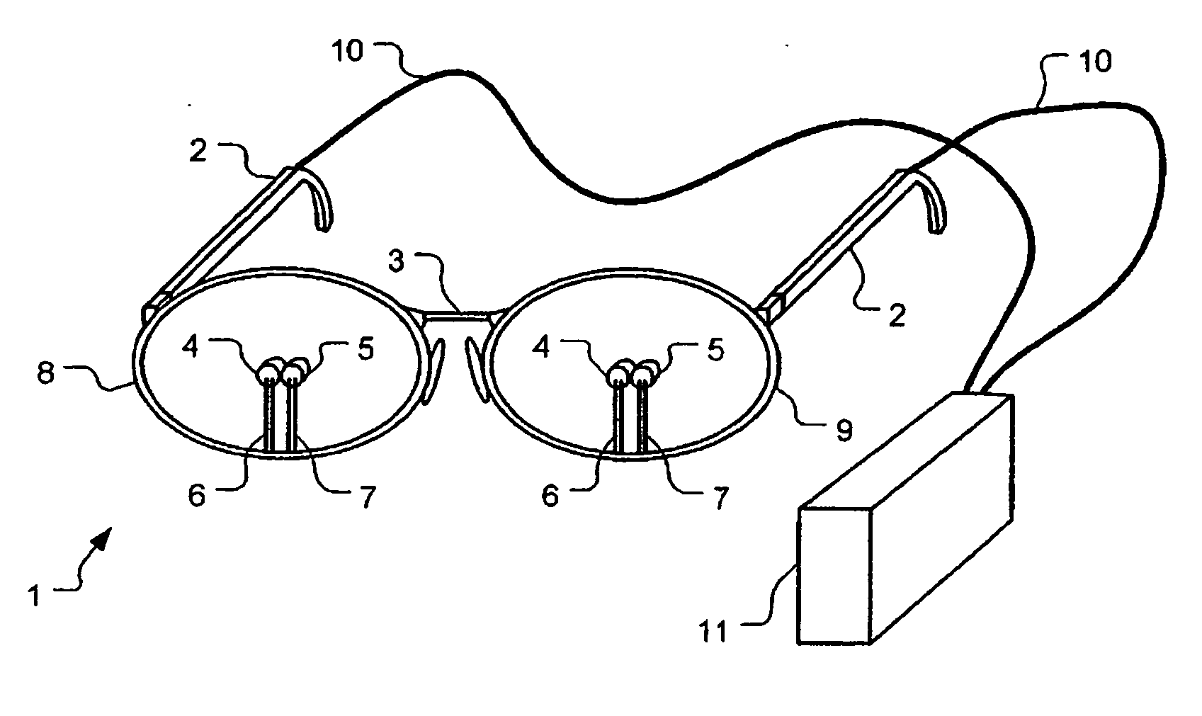
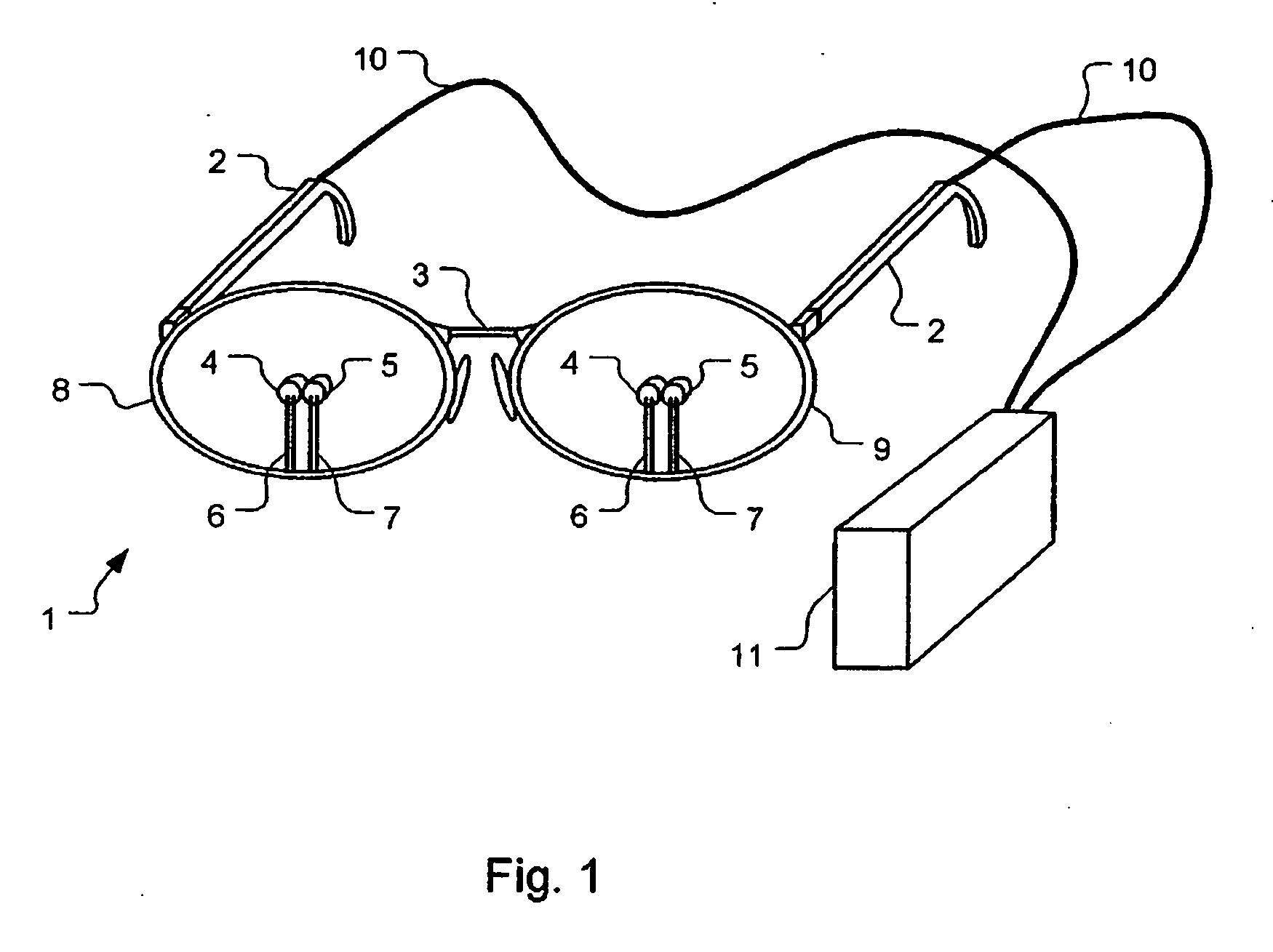
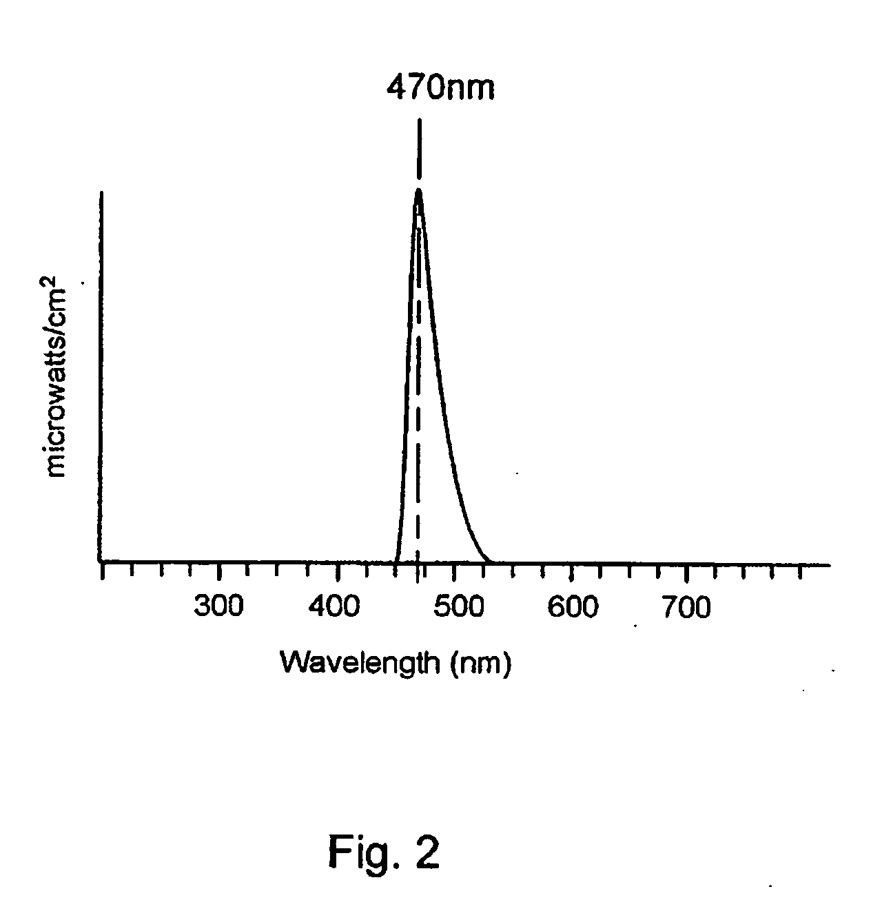
[0061]FIG. 1 shows an apparatus for administering light stimulation to effect re-timing of the human body clock according to a first preferred embodiment. In the illustrated embodiment, the apparatus takes the form of a substantially conventional eyeglass frame 1 having ear stems 2 and a nose bridge 3. The glasses are worn on the head of a patient in the conventional manner. Two light emitting elements, shown as light emitting diodes 4, 5, are mounted on bifurcated stems, 6, 7 to be located approximately central to the rims 8,0 of the eyeglass frame 1. The eyeglasses shown here are fitted with lenses. The light emitting diodes 4, 5 are aimed directly at the pupil of the adjacent eye and are positioned at about 12 mm from the eye surface. The light emitting diodes 4, 5 are a high intensity light emitting diode such as a Kingbright T-1 (3 mm) solid state diode that provides a dominant wavelength of about 470 nm.

[0062] As is shown, the ligh...


PUM


Abstract

An apparatus for administering light to effect re-timing of the human body clock is disclosed. In one form, the apparatus includes two pairs of light emitting diodes having an emission wavelength in the range 450 nm to 530 nm and a frame adapted to be worn on the face of a wearer. The frame is arranged to support the two pairs of light emitting diodes so that one pair of the light emitting diodes is supported adjacent a surface of each eye of the wearer. The light emitting diodes of each pair project a light output that illuminates a different area of the retina of a respective eye and are spaced apart so as to provide a viewing zone therebetween.

Description

RELATED APPLICATION [0001] This application is a continuation under 35 U.S.C. 111(a) of PCT / AU2004 / 000559, filed Apr. 30, 2004, and published in English on Nov. 11, 2004 as WO 2004 / 096364 A1, which claims priority under 35 U.S.C. 119 to Australian Application Nos. 2003203967, filed May 1, 2003 and 2003905846, filed Oct. 24, 2003, which applications and publication are incorporated herein by reference.FIELD OF THE INVENTION [0002] This invention relates to the presentation of relatively intense visual light stimulation for the treatment of circadian rhythm disorders including sleep onset insomnia and early morning awakening insomnia, jet-lag, shift work fatigue, winter depression or seasonal affective disorder (SAD), and other conditions requiring the re-timing of human circadian rhythms (24-hour body clock). BACKGROUND OF THE INVENTION [0003] The timing of the body's circadian rhythms very strongly determines our best times to sleep and to be awake and alert. The anatomical pathways...

Claims


Application Information

Patent Timeline
Patent Type & Authority Applications(United States)
IPC IPC(8): A61N5/06A61M21/00
CPCA61M21/00A61M2021/0044A61N2005/0648A61N2005/0651
Inventor LACK, LEONWRIGHT, HELEN
Owner RE TIME PTY LTD
Why Eureka
Try Eureka