
Protective cover and patient security apparatus

a technology for protecting covers and patient wounds, applied in the field of protective covers and patient security devices, can solve the problems of not being usable, affecting the immediate access of open wounds, and not being able to use,

Inactive Publication Date: 2006-06-29
TIDI CFI PROD
View PDF45 Cites 8 Cited by
  • Summary
  • Abstract
  • Description
  • Claims
  • Application Information

AI Technical Summary

Benefits of technology

"The invention is a protective sheet designed to be placed on a patient support for medical imaging procedures. The sheet is made of waterproof material and has two flaps that can be secured to the support surface. The sheet also has patient restraining flaps to hold the patient in place. The sheet is designed to prevent the escape of fluids and to provide a secure and comfortable surface for the patient. The materials used in the sheet are strong and waterproof, and can be easily cleaned. The technical effects of the invention are improved safety and comfort for patients and consistent and thorough cleaning of the patient support equipment."

Problems solved by technology

However, in emergency medicine procedures strapping cannot always be used because such strapping applies mechanical loads to the patient that may not be suitable for a patient having fractures or other injuries.
Strapping also may interfere with the immediate access to open wounds and, occasionally, may not be usable because of foreign objects embedded in or projecting from the patient's body.
When side rails of these kinds are provided on a medical imaging support which also serves as a gurney or trolley, such side rails interfere with imaging in the lateral and oblique directions because of the radiolucent opacity of metals and the artifact-causing abrupt density transition at the metal / air boundaries.
Even though such side rails may be made of carbon fiber composites to improve their radiolucency, the additional cost of such materials is substantial.
This may allow those body parts to extend into pinch points and danger zones associated with adjacent medical imaging equipment, or otherwise create injury-prone situations.
This is of particular concern in emergency medicine venues where the patient may not be able to cooperate with medical personnel by remaining stationary.
These requirements for removability and gap free mounting can be especially troublesome in meeting the need for haste in the installation of such rails inasmuch as some portions of the patient's body may not be clear at the installation zone, thereby creating a pinch point situation when a solid plate rail is moved into its installed position.
Another problem encountered with removable, rigid side rails is that they present a physical location challenge when they are not in their installed position.
If such rails are fully removable they tend to be set aside and left behind when a patient trolley or gurney is moved, thereby disrupting subsequent usage of the trolley or gurney until the missing side rails are retrieved.
If a side rail is hinged or otherwise mounted to the support so as to swing outward and downward to a storage position below the support top, the raising and lowering of such a side rail may be impossible while the trolley or gurney is located closely alongside another patient support, such as a stretcher or a surgical table, to which a patient must be moved for further treatment.
Such downward storage positions also may interfere with the close passage of medical imaging equipment under the support top, inasmuch as such imaging equipment often must be provided with a clearance below the support top for medically acceptable imaging precision.
If such rails are mounted so as to swing downward into a pocket in or below the support top, or are otherwise designed to be lowered without taking up any space either below or beyond the top, the pocket in the support inevitably causes the top to have an inconsistent radiolucent density across its area which creates artifacting for anterior-posterior imaging.
Such pocket designs also may involve an unacceptable compromise of structural strength, particularly in view of the necessity of making support tops increasingly stronger to support increasingly heavier patient populations while still maximizing such tops' radiolucency characteristics.
A related disadvantage of rigid side rails of all types is that their removal, storage, and reinstallation require so much time that patient survival may be compromised, especially in emergency medicine situations.
Another problem with rigid side rails of all types that are fully removable is that they may not be safe for use on gurneys or trolleys for reception of patients from a helicopter.
Consequently, if a rigid side rail should inadvertently be raised into the path of movement of a rotor blade, a catastrophe could occur.
A still further problem with rigid side rails of all types, and particularly those used in emergency medicine situations, is that their rigid nature can interfere with the positioning of certain patients who must be imaged while being equipped with devices such as emergency splints or backboards which, even though they need not be imaged themselves, may project beyond the boundaries of the patient's body to such an extent that the side rails cannot be installed when the patient is optimally positioned.
Quite apart from the foregoing undesirable characteristics of currently available patient security apparatus such apparatus presents problems in coping with contamination prevention, cleaning, and physical damage.
It is well known that general medical imaging tables accumulate biological contamination in film or solid form from normal contact with patients' skin, hair, and clothing and must be cleaned periodically.
At times, large quantities of blood and other fluids can contaminate the area around an emergency medicine patient during the initial period of treatment.
If such fluids are not captured close to the patient, they may run off the table and contaminate lower parts of the gurney or trolley, associated medical imaging equipment, or the floor under such equipment.
In addition, emergency medicine patients also sometimes arrive at a treatment site with foreign objects or broken bones projecting from their bodies in such manner as to present cutting or puncturing hazards to any vulnerable equipment at the site.

Method used


Image

  • Protective cover and patient security apparatus
  • Protective cover and patient security apparatus
  • Protective cover and patient security apparatus

Examples


Embodiment Construction

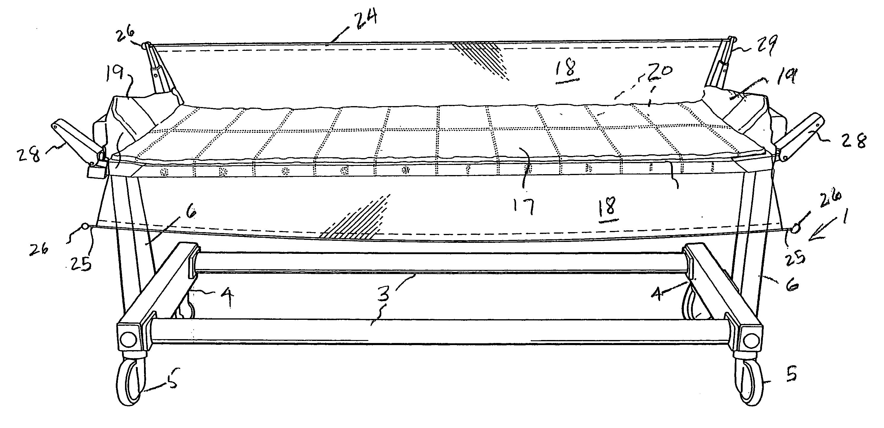
[0026] A sheet assembly constructed in accordance with the preferred embodiment is adapted for use with a patient support 1 (FIGS. 6 and 7) having a frame 2 composed of parallel, spaced rails 3 joined at corresponding ends by cross bars 4 equipped with wheels 5. The frame 2 mounts vertically adjustable uprights 6 provided at their upper ends with supports 7 which mount a patient supporting table 8 of such length and width as to enable a patient to be supported in supine position. The supports 7 are pivotable about a horizontal axis by means of a pivot pin 9, thereby enabling the opposite ends of the patient's support 8 to occupy different vertical levels.

[0027] The patient support 1 is intended to be illustrative of any one of a number of different kinds of patient supports. It can be a gurney, a trolley, an operating table, part of a radiologic imaging table, or any other appropriate support of the kind used for supporting and / or transporting a patient.

[0028] A sheet assembly con...


PUM


Abstract

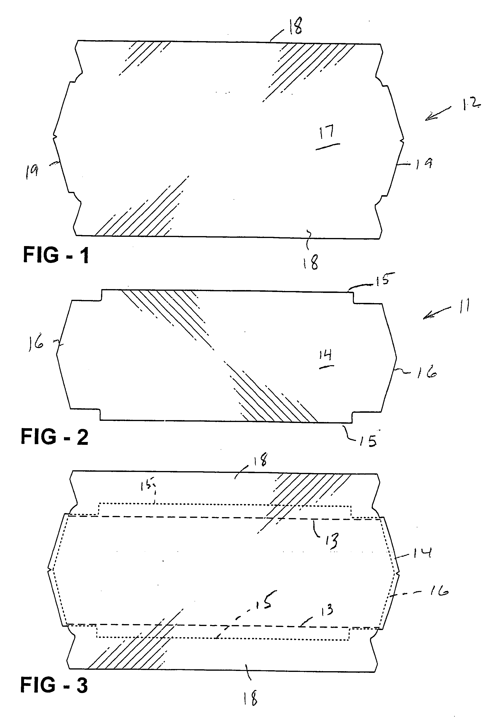
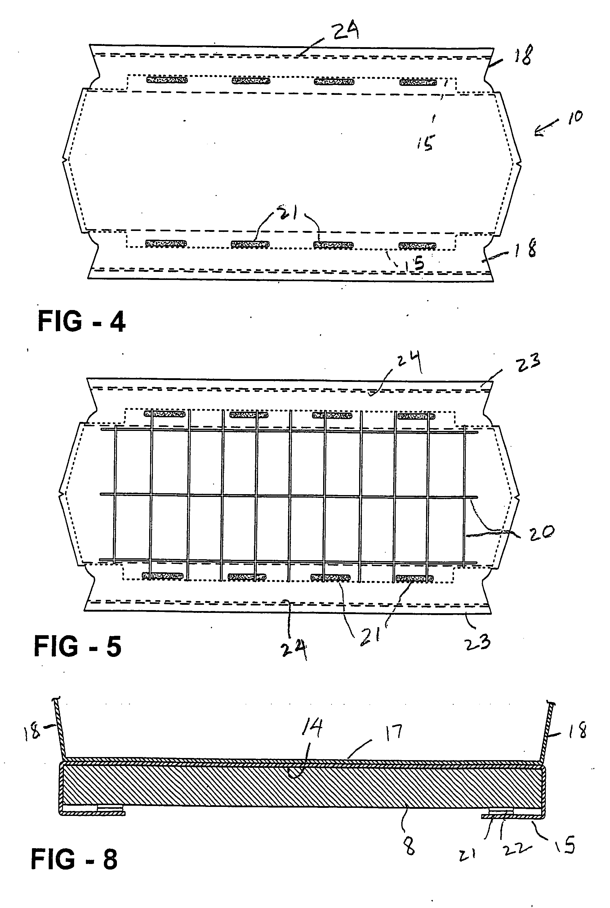
A sheet assembly adapted to occupy a position beneath a patient and an upper surface of a patient support. The assembly has overlying upper and lower pliable sheets formed of a material of low density gradient and having central sections from which upper and lower flaps extend laterally. The lower flaps may be secured to the patient support and the upper flaps may be elevated to and maintained at a level above that of the upper surface of the patient support, thereby providing a safeguard against the patient's falling off the support surface.

Description

[0001] This invention relates to apparatus for underlying a patient on a support surface to protect such surface and restraining such patient from falling off the surface. BACKGROUND OF THE INVENTION [0002] Patient supports for use in performing X-ray or other imaging procedures conventionally are provided with casters and other features enabling them to serve as gurneys or trolleys for supporting and transporting a patient. Normally, it is desirable to provide such supports with patient security means for preventing a patient from falling or sliding off the support while imaging procedures are being performed or during transport of the patient. In general medical imaging applications patient security often is provided by means of strapping systems. However, in emergency medicine procedures strapping cannot always be used because such strapping applies mechanical loads to the patient that may not be suitable for a patient having fractures or other injuries. Strapping also may interf...

Claims


Application Information

Patent Timeline
Patent Type & Authority Applications(United States)
IPC IPC(8): A47G9/00A47C21/08
CPCA61B6/0428A61G1/04A61G7/0507A61G13/102A61G2007/051A61G2007/0515A61G2007/0518A61G7/051A61G7/0515A61G7/0518
Inventor SCHAEFER, JOHN W.
Owner TIDI CFI PROD
Learn More