Carbon dioxide driven electrical power plant

Inactive Publication Date: 2006-06-29
IVERSON DONALD
View PDF13 Cites 9 Cited by
  • Summary
  • Abstract
  • Description
  • Claims
  • Application Information

AI Technical Summary

Benefits of technology

[0011] The container has an aerodynamically shaped bottom area for reducing frictional drag caused by the travel of the

Problems solved by technology

The main difference with this type of energy production is the li

Method used


Image

  • Carbon dioxide driven electrical power plant
  • Carbon dioxide driven electrical power plant
  • Carbon dioxide driven electrical power plant

Examples


Embodiment Construction

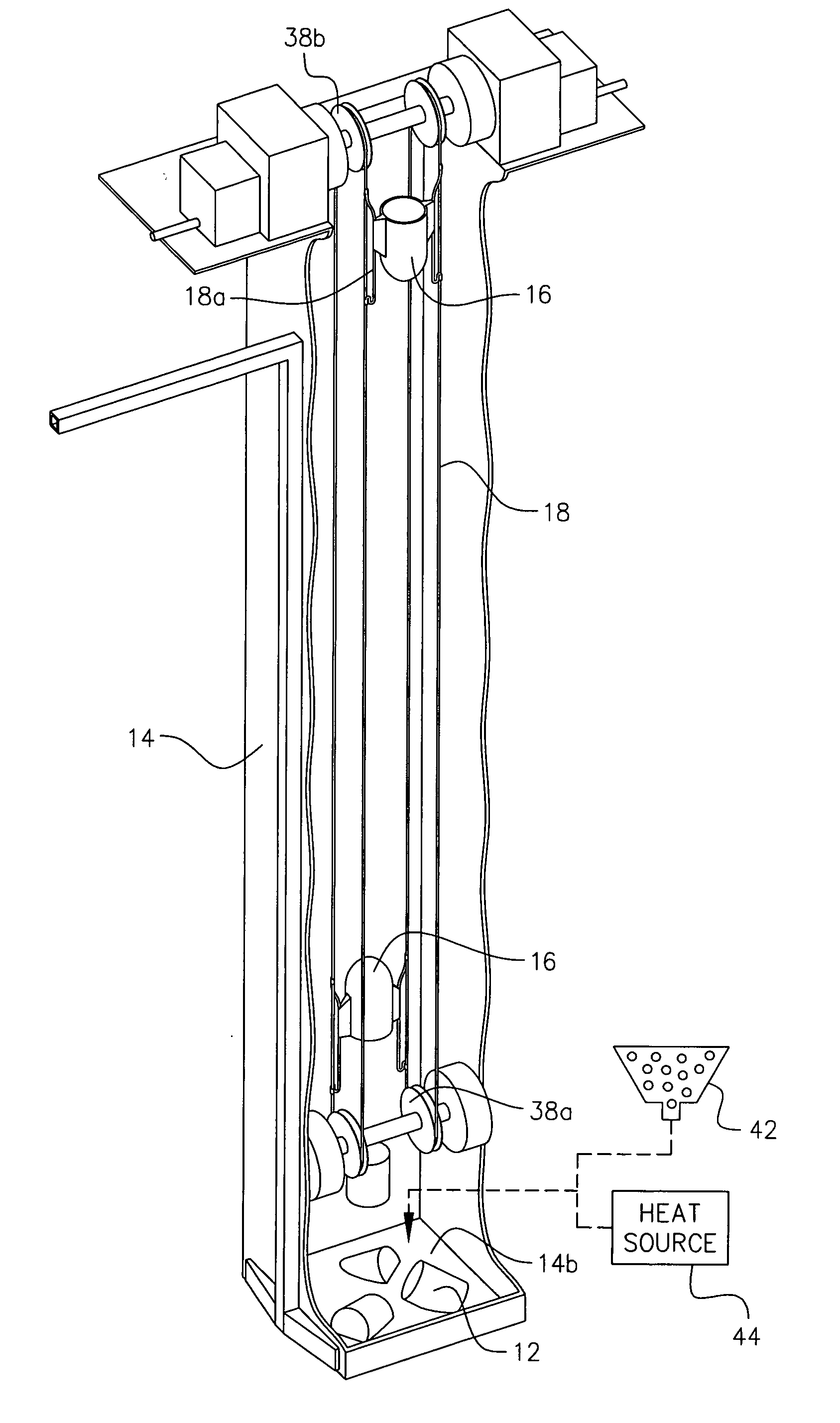
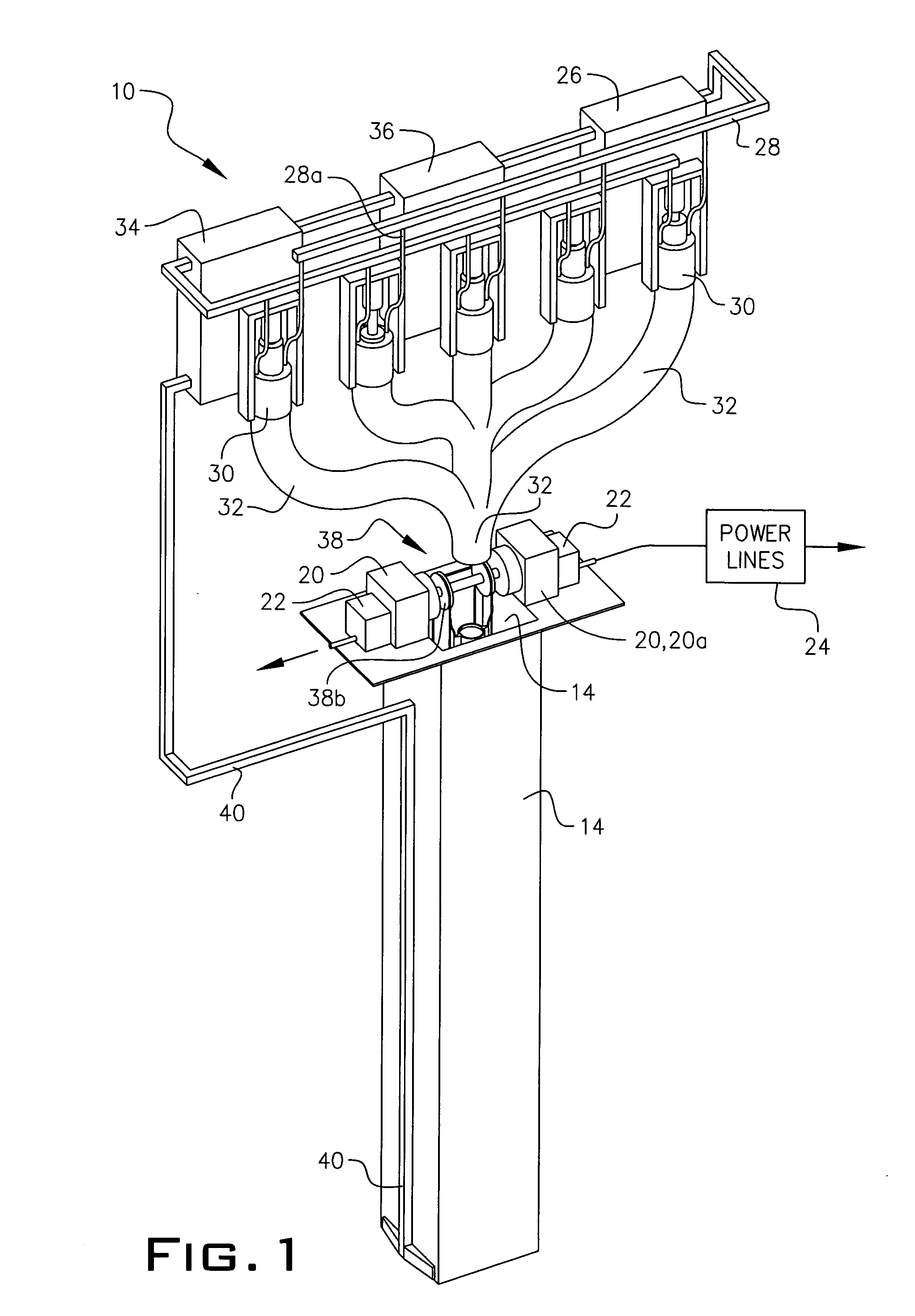
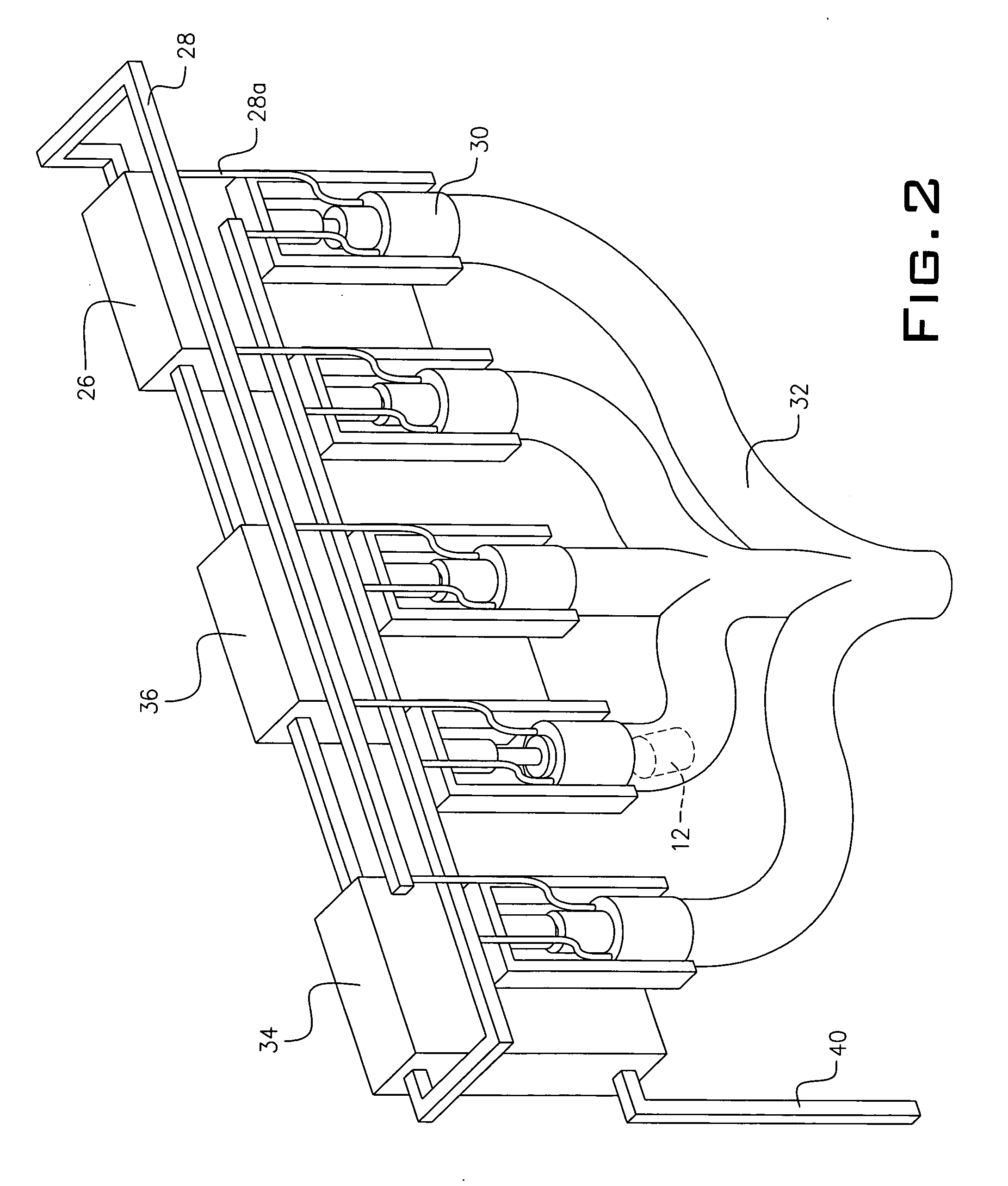
[0028] Referring now to the drawings, FIGS. 1-4 disclose conceptually an example of the application of the present invention, which is a carbon dioxide driven electrical power plant system, depicted generally as 10.

[0029] The carbon dioxide driven power plant 10 uses heavy blocks of dry ice 12 falling down a vertical shaft 14 in a container 16 attached to a cable circuit or system 18 to create the torque necessary to operate one or more an electric generators 20. Dry ice 12 is used, as opposed to water ice or metal, because once the block reaches the bottom of the shaft 14, it will sublimate and become a gas, which is easy to bring back to the surface and recycle. This invention can be broken down into three main systems: carbon dioxide recycling, vertical shaft, and energy production, which when operating symbiotically, will produce electrical power without pollution, in a closed system which can be added to the local power grid using transformers 22 and power lines 24.

[0030] The...


PUM


Abstract

A carbon dioxide driven electrical power plant for integration with surrounding utilities. This power plant uses the earth's gravitational effect on mass, provided by solid carbon dioxide, to create work. This work is then harnessed in the form of electrical power. The carbon dioxide gas released during the formation of dry ice and during the sublimation stage when the dry ice is dispensed at the bottom of a vertical shaft is recycled through a gas filtration system and liquefaction system to create additional dry ice.

Description

[0001] This application relates to alternative sources of energy production in the form of the production of electricity using carbon dioxide blocks. BACKGROUND OF THE INVENTION [0002] There are many alternative sources of energy for the generation of electricity such as windmills, solar panels, hydroelectric dams, etc. All have several associated problems such as number of windmills required, area of land needed for the windmills, obstruction of waterways, and environmental problems. The present invention attempts to solve several problems plaguing the energy sector at present, including non-renewable resource consumption, hazardous environmental waste, inconsistent reliability, and production inefficiency. [0003] The present invention takes into consideration technologies employed in energy production facilities, mineshaft drilling and deep earth conditions, carbon dioxide filtering and condensing, cable and elevator innovations, general aerodynamics, and physics. SUMMARY OF THE I...

Claims


Application Information

Patent Timeline
IPC IPC(8): F17C7/02F25D15/00F25D23/12F25J1/00
CPCF03G3/04
Inventor IVERSON, DONALD
Owner IVERSON DONALD
Why Eureka
Try Eureka