Instrumentation and method for monitoring change in electric potential to detect crack growth

a technology of electric potential and measurement method, applied in the direction of instruments, using mechanical means, resistance/reactance/impedence, etc., can solve the problems of cracks developing and propagating, affecting the lifetime of machine components, and invalidating tests, so as to achieve more sensitive measurement of fatigue cracking

Inactive Publication Date: 2006-06-29
GENERAL ELECTRIC CO
View PDF31 Cites 9 Cited by
  • Summary
  • Abstract
  • Description
  • Claims
  • Application Information

AI Technical Summary

Benefits of technology

[0011] One advantage of the present invention is that it provides instrumentation and methods to measure fatigue cracking without damaging the specimen to be tested in a manner that interferes with the testing.
[0012] Another advantage of the present invention is that it provides instrumentation that can be used to obtain a more sensitive measurement of fatigue cracking by measuring crack growth in smaller increments than in current state of the art technology.
[0013] Sti

Problems solved by technology

Over time, thermal and mechanical stresses resulting from cyclic loading may cause machine components to fatigue and develop cracks.
The rate at which cracks develop and propagate has a direct impact on the lifetime of machine components.
One problem associated with conventional instruments, such as the one shown in FIG. 1, is that even if the sensing leads are attached to the surface of the specimen with a only a low power weld, some small cracks or weak spots result in the specimen at the welds which invalidates test results.
The ability to measure crack propagation is limited to starter cracks larger than 4 mils deep and 8 mils wide, as interference develops from the weld

Method used


Image

  • Instrumentation and method for monitoring change in electric potential to detect crack growth
  • Instrumentation and method for monitoring change in electric potential to detect crack growth
  • Instrumentation and method for monitoring change in electric potential to detect crack growth

Examples


Embodiment Construction

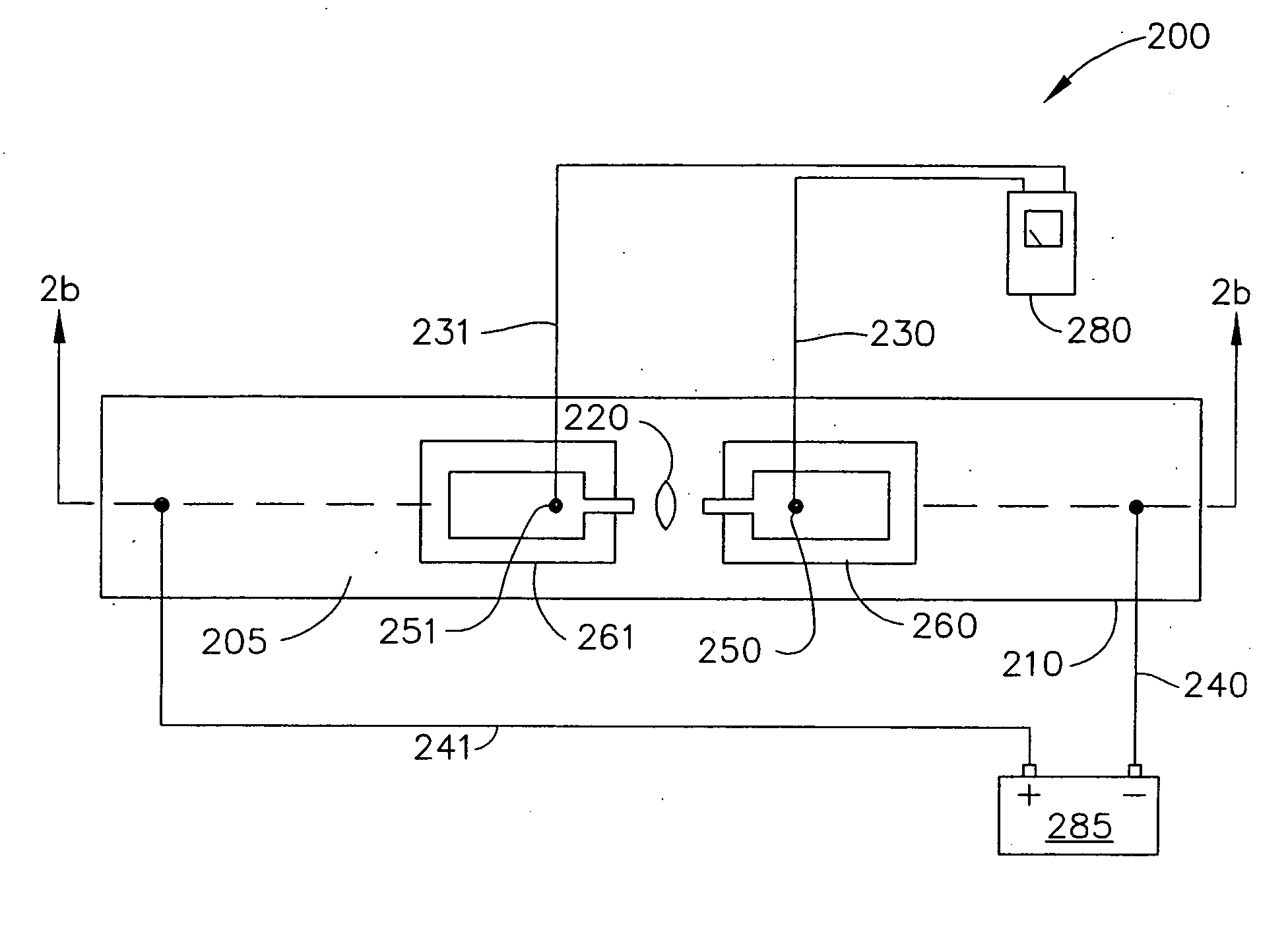
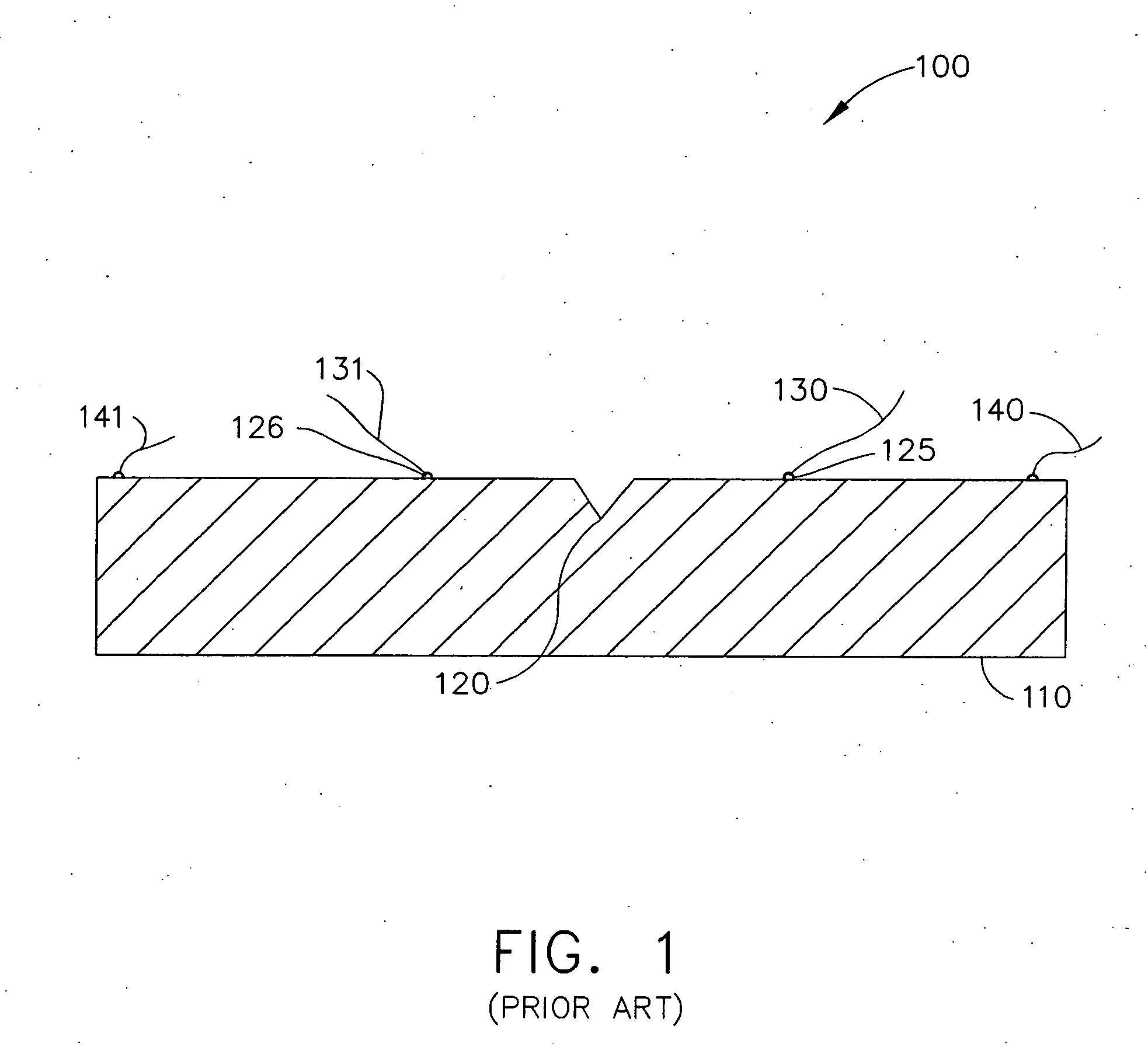
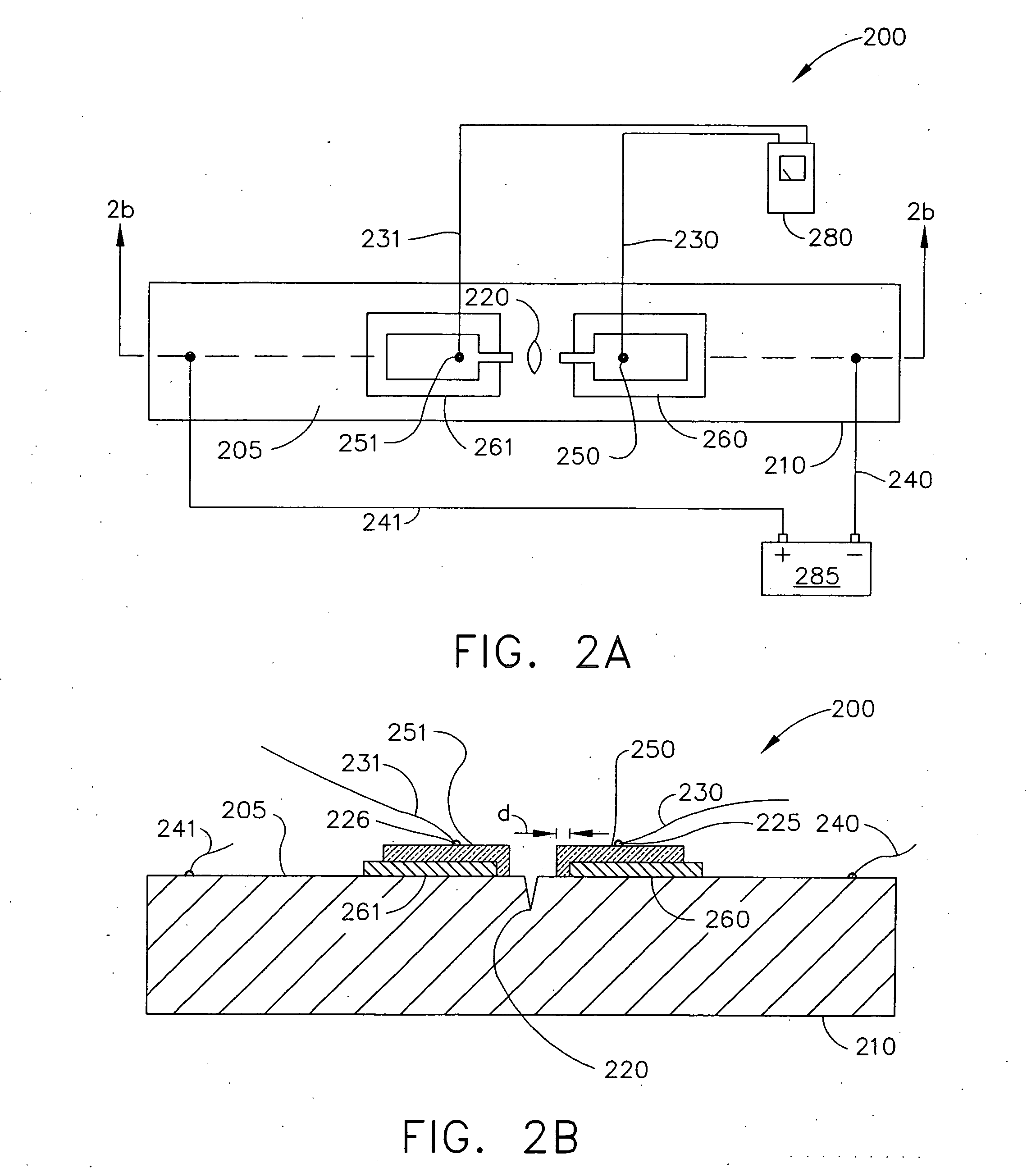
[0019] The invention is directed to instrumentation and methods for monitoring electric potential across a predetermined starter crack to detect crack growth of the starter crack in a test specimen that overcomes problems encountered by prior instrumentation and methods. The present invention allows cracks of smaller initial size to be monitored while allowing cracks to be monitored with greater sensitivity, thus measuring smaller growth increments. To overcome the limitations of the prior art and avoid inducing damage to the specimen during preparation, which is a source of limitation seen in the prior art, sensing leads are not attached directly to a test specimen to be studied for crack growth.

[0020] According to exemplary embodiments of the present invention, sensing leads are in electrical contact with the specimen to measure a change in electric potential across the crack via a conductive intermediary in the form of a thin film of conductive material. The conductive material ...


PUM


Abstract

Instrumentation for monitoring crack growth using a change in electric potential across a starter crack as the crack propagates is disclosed. The instrumentation includes a specimen of a material to be analyzed for crack growth propagation having a surface with a starter crack formed therein, a plurality of current leads to pass electric current through the specimen, a layer of insulating material disposed on each of opposite sides of the crack, a layer of conductive material disposed on each layer of insulating material, where a portion of each layer of conductive material is in electrical contact with the first specimen surface, and a pair of sensing leads, one sensing lead attached to each layer of conductive material. A method for using the instrumentation to monitor crack growth by measuring is also disclosed.

Description

FIELD OF THE INVENTION [0001] The present invention is directed to instrumentation and methods for measuring crack growth during fatigue testing of materials and is more particularly directed to instrumentation and methods for measuring crack growth during fatigue testing of materials by measuring a change in electric potential across a crack using thin films of insulators and conductors to attach leads to the materials being tested. BACKGROUND OF THE INVENTION [0002] Machines, particularly machines with rotating parts, such as gas turbine engines, typically undergo cyclic loading during operation. Over time, thermal and mechanical stresses resulting from cyclic loading may cause machine components to fatigue and develop cracks. The rate at which cracks develop and propagate has a direct impact on the lifetime of machine components. By monitoring the growth of cracks on test specimens of machine components, it may be possible to better estimate the useful lifetime of machine compone...

Claims


Application Information

Patent Timeline
IPC IPC(8): G01N3/32
CPCG01N3/066G01N2203/0066G01N2203/0073G01N2203/027G01N2203/0617
Inventor WRIGHT, PHILEMON KENNARD III
Owner GENERAL ELECTRIC CO
Why Eureka
Try Eureka