Balance shaft for a reciprocating piston engine

Inactive Publication Date: 2006-06-29
MAGNA DRIVE GRAIN AG &
View PDF6 Cites 7 Cited by
  • Summary
  • Abstract
  • Description
  • Claims
  • Application Information

AI Technical Summary

Benefits of technology

[0006] According to the invention, the foregoing object is achieved by virtue of the fact that the compensating weight surrounds the compensating shaft with its edge zones (as described in WO 01/29447 A1) and a window is formed therebetween in the longitudinal direction, in which an elastic element is provided, which is supported on the compensating shaft in the circumferential direction. The connection is thus soft in the circumferential direction and hard in the radial direction, which is desirable on account of the unbalance. In addition to the other advantages, the window moreover allows enough space for a spring damper unit or for an elastic element made of plastic. The latter makes it possible to produce a compensating weight with a closed cylindrical contour, which minimizes its splashing losses. The fact that only the compensating masses themselves vibrate

Problems solved by technology

The latter are, on account of the clearances in their drive and the small torque transmitted via it, a noise source which is particularly difficult to control; moreover, great load with a changing sign is

Method used


Image

  • Balance shaft for a reciprocating piston engine
  • Balance shaft for a reciprocating piston engine
  • Balance shaft for a reciprocating piston engine

Examples


Example

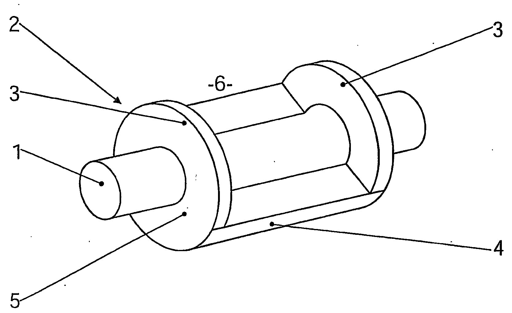
[0014] In FIG. 1, a shaft is designated by 1 and a compensating weight by 2. The two together form a compensating shaft, which can also have more than one compensating weight 2. Here, the compensating weight 2 is of the type known from WO 01 / 29447, with two edge zones 3, which surround the shaft 1 like suspenders, and an eccentric unbalance mass 4. A window 6 is thus formed on that side of the shaft 1 facing away from the unbalance mass 4. However, the compensating weight could also be of any other shape, for instance a closed eccentric body. It is essential that the compensating weight 2 is fastened on the shaft 1 with an elastic bushing 5 interposed. Here, the elastic bushing 5 is in the form of a cylinder jacket, which is cut out in the window 6. It is made from a material which is elastic above all in the circumferential direction, preferably a rubber-like plastic. The connection between the elastic bushing 5 and the surface parts bearing against it of the shaft 1 and the compen...


PUM


Abstract

In a compensating shaft for reciprocating piston engines with at least one compensating weight (22) connected torsionally elastically to the compensating shaft (21), effective noise reduction is achieved by using an elastic element, preferably one (25) made of plastic of elasticity which is graduated in the circumferential direction, the hard central part (26) having a connection (15) to the compensating shaft (11) which is firm in the circumferential direction, and the soft part (31) bearing against the compensating weight (22).

Description

BACKGROUND OF THE INVENTION [0001] The invention relates to a compensating shaft for reciprocating piston engines with at least one compensating weight with an eccentric center of gravity, the compensating weight being connected torsionally elastically to the compensating shaft. In modern internal combustion engines, compensating shafts are used to reduce vibrations and running noises. However, their effect and success is satisfactory only when the compensating shaft unit itself also runs in a quiet and vibration-free way. [0002] Vibrations of the compensating shaft unit can be excited by the moving masses of the engine and by its rotational irregularity. The latter are, on account of the clearances in their drive and the small torque transmitted via it, a noise source which is particularly difficult to control; moreover, great load with a changing sign is exerted on the teeth by virtue of the rotational irregularity. Minimizing the tooth clearances is problematic on account of the ...

Claims


Application Information

Patent Timeline
IPC IPC(8): F02B75/06F16C3/00F16F15/14F16F15/26
CPCF16F15/1457Y10T464/50F16F15/264F16F15/1442F16F15/322
Inventor FRIEDRICH, CHRISTIAN
Owner MAGNA DRIVE GRAIN AG &
Why Eureka
Try Eureka