Thread control for welding wire

a technology of thread control and welding wire, which is applied in the direction of welding accessories, welding apparatus, manufacturing tools, etc., can solve the problems of electrode sticking out, low quality weld bead initial formation, and difficulty in achieving quality control during the initial formation of weld bead, so as to facilitate the diagnostic and/or calibration functions of welders, facilitate inventory control and/or monitoring of welding wires, and reduce human error

Inactive Publication Date: 2006-06-29
LINCOLN GLOABL
View PDF6 Cites 37 Cited by
  • Summary
  • Abstract
  • Description
  • Claims
  • Application Information

AI Technical Summary

Benefits of technology

[0022] Still yet another and/or additional object of the present invention is the provision of a welding wire positioning mechanism that decreases human error in the selection of proper welding wire stick-out from a welding gun.
[0023] A further and/or additional object of the present invention is the provision of a weldi

Problems solved by technology

Although the control of these welding parameters greatly facilitates in the consistent formation of a high quality weld bead after the beginning of the welding process, quality control during the initial formation of the weld bead is more difficult to achieve.
One of the contributing factors associated with the inconsistent quality of the weld bead at the start of a welding operation is the stick-out distance of the electrode at the beginning of the welding operation.
If the stick-out distance is too great or too small, a low quality weld bead will initially be formed.
The problem associated with proper electrode stick-out occurs principally in two situations, namely 1) when a supply of welding wire is depleted and a new wire supply is fed into the welding gun, and 2) at the beginning of each repetitive welding operation.
This manual process of setting the stick-out distance is a time-consuming operation and also resulted in some operator error when the proper distance was not selected.
Furthermore, the end portion of some of the welding electrode was typically cutoff to obtain the desired stick-out distance, thus resulting is waste of the welding w

Method used


Image

  • Thread control for welding wire
  • Thread control for welding wire
  • Thread control for welding wire

Examples


Embodiment Construction

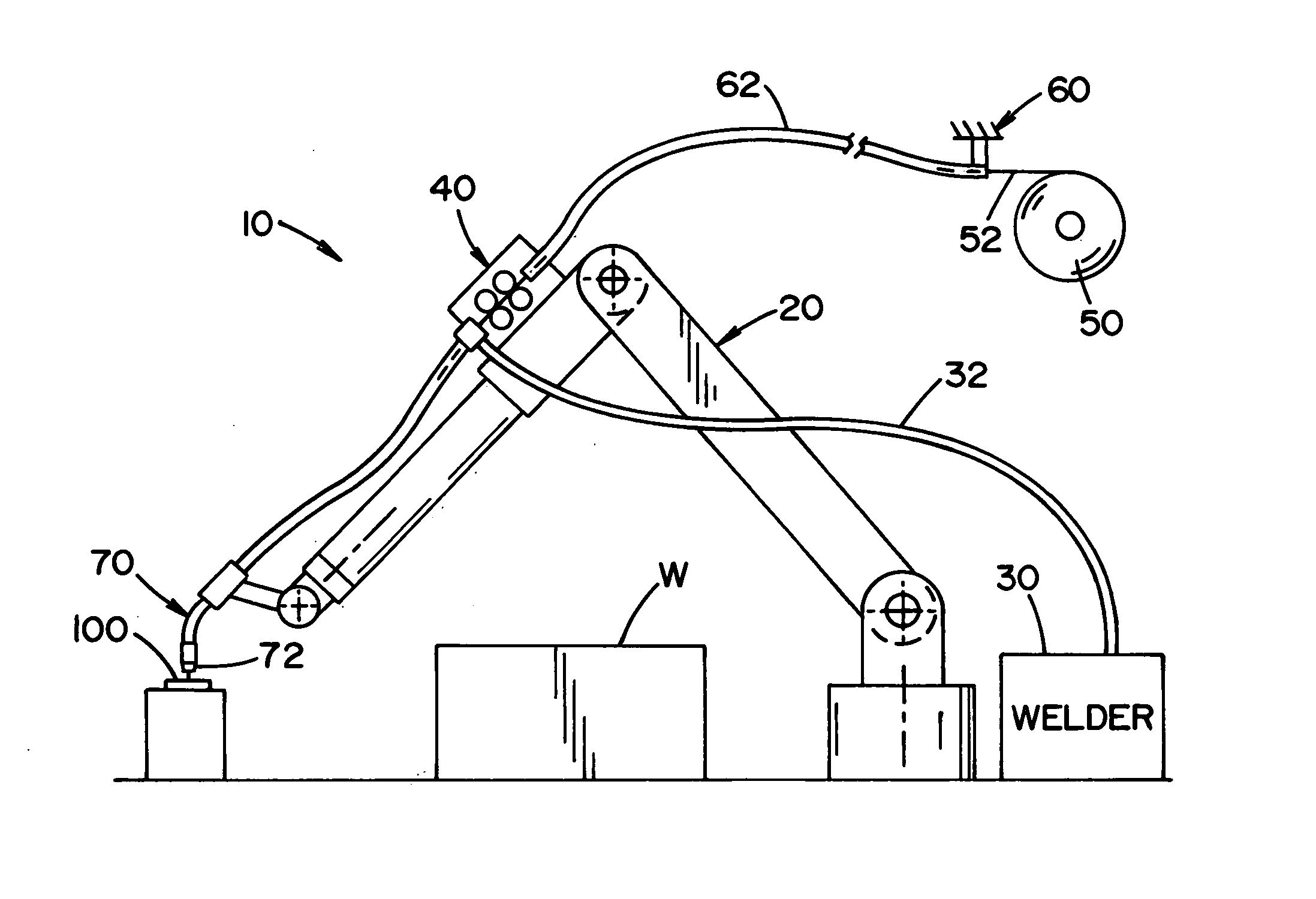
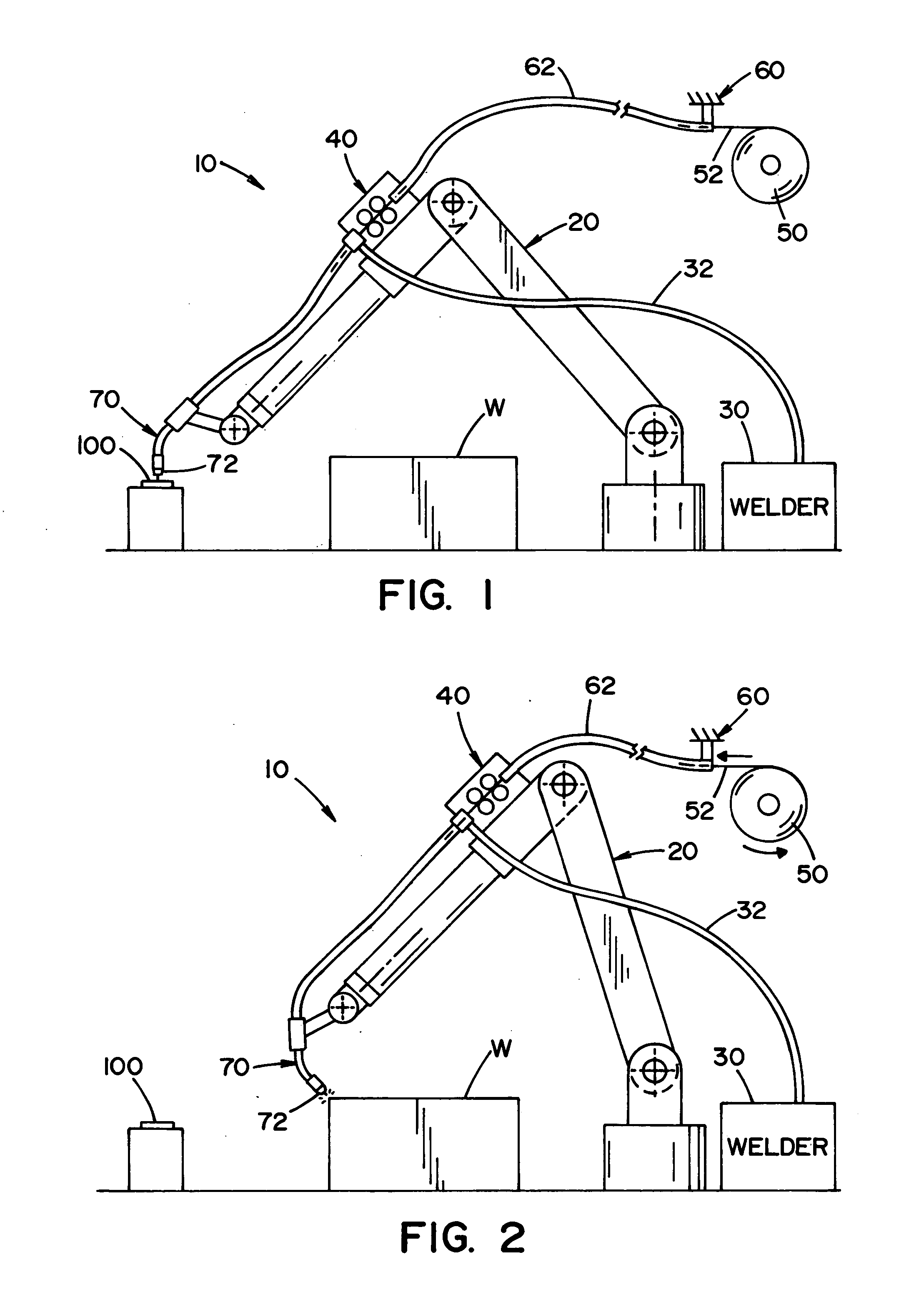
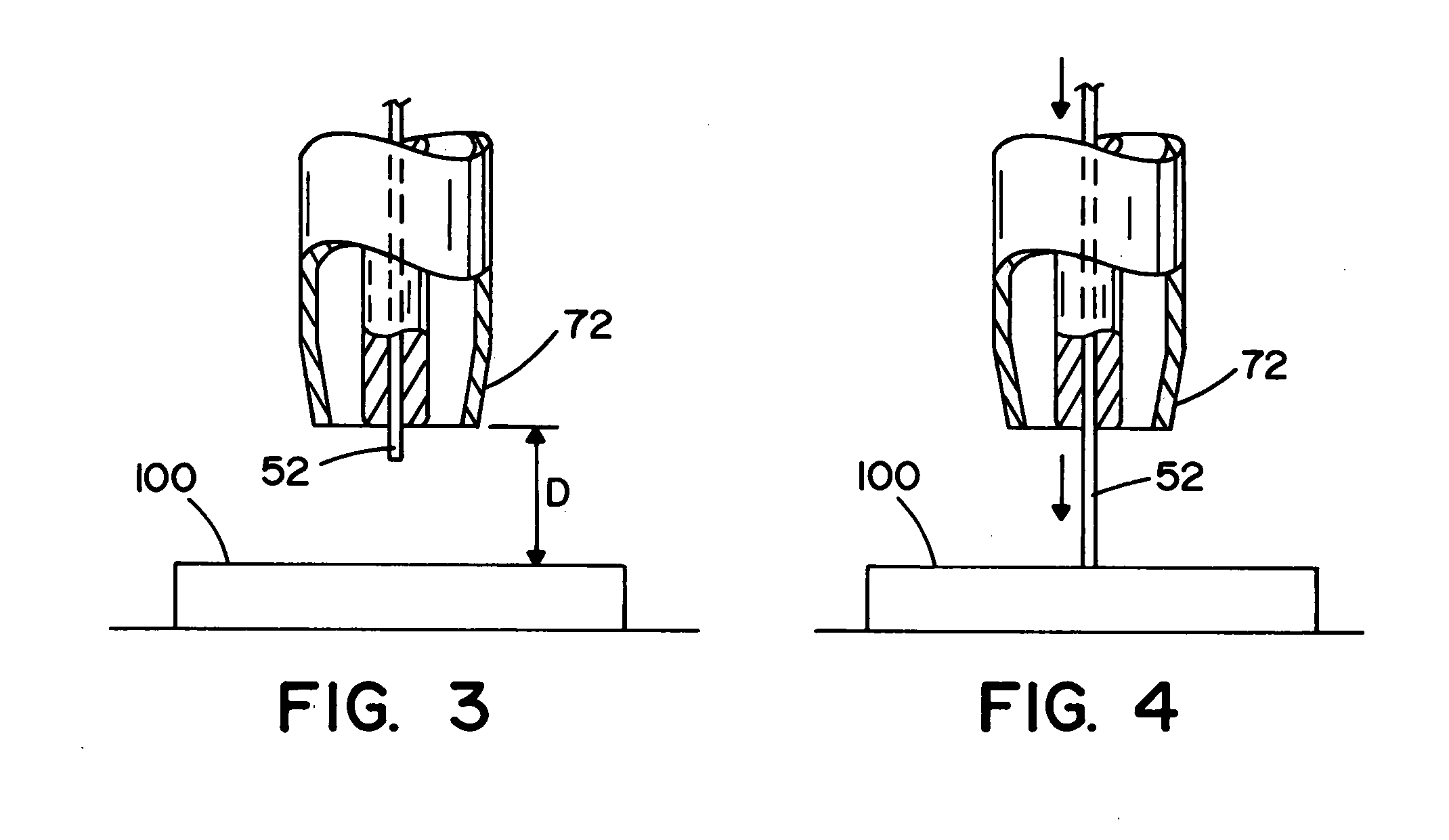
[0031] Referring now to the drawings, wherein the drawings are for the purpose of illustrating the preferred embodiments of the invention only and not for the purpose of limiting the same, FIGS. 1-4 illustrate a robotic welder system 10 that includes a robotic arm 20, a welding power source 30, a robot control 40, a welding wire reel 50 that includes a source of welding wire 52, and a wire feeder 60. The robotic welding system can include other components such as, but not limited to, shield gas source, an external monitoring and / or control interface, etc. The robotic welding system is particularly applicable for MIG welding, pulsed MIG welding, and MAG welding for high output and / or industrial welding environments such as those more commonly encountered in various types of manufacturing facilities; however, it will be appreciated, that the welding system can be used in other types of welding operations.

[0032] The robot control 40 is designed to control the movement of the welding a...


PUM

PropertyMeasurementUnit
Feed rateaaaaaaaaaa
Speedaaaaaaaaaa
Distanceaaaaaaaaaa

Abstract

A wire feeding control mechanism and method to obtain a certain stick-out of welding wire from a tip of a welding gun.

Description

[0001] The present invention relates to the art of welding, and more particularly to a method and an apparatus for controlling the feeding of welding wire from a welding wire supply through a welding gun of a welding system. BACKGROUND OF THE INVENTION [0002] Automated welding applications continue to increase in popularity. These automated welding operations are commonly used for high output, repetitive welding applications that commonly occur in various types of industrial applications (e.g., automotive industry, etc.). Welding systems such as automatic or robotic welders are commonly used in machine shops, automobile manufacturing facilities and other industrial facilities. The repetitive nature of the welding operation lends itself to a programmed operation of the welder to achieve a consistent and high quality weld bead for each repetitive welding operation. [0003] In order to achieve the desired consistency in quality and appearance of the weld bead for each repetitive welding...

Claims


Application Information

Patent Timeline
IPC IPC(8): B23K9/12
CPCB23K9/124B23K9/125B23K9/32
Inventor LIPNEVICIUS, GEOFFREY MICHAEL
Owner LINCOLN GLOABL
Why Eureka
Try Eureka