Seat air conditioner for vehicle

a technology for air conditioners and seats, which is applied in the direction of chairs, heating types, ventilation systems, etc., can solve the problems of inferior isolation effect of seal packing, inferior vibration isolation effect of blower units, and inferior vibration isolation effect of felt, so as to improve the durability of the vibration isolation support construction reduce the impact of the blower uni

Inactive Publication Date: 2006-06-29
DENSO CORP
View PDF12 Cites 60 Cited by
  • Summary
  • Abstract
  • Description
  • Claims
  • Application Information

AI Technical Summary

Benefits of technology

[0011] In view of the above-described and other disadvantages, it is an object of the present invention to provide a vehicle seat air conditioner, in which a transmission of vibration excited by a blower unit is restricted and an absorption of relative displacement of the blower unit with respect to seat spring members and a cushion member is improved. The blower unit is provided with a vibration-isolating support construction having a substantial endurance capacity.
[0014] Moreover, the accordion duct made of the rubber has a satisfactory vibration-isolating effect, to restrict the vibration of the first blower unit from being transmitted to the cushion member through the air discharge duct.
[0016] Because the vibration-isolating resilient member made of the resilient material with the smaller friction coefficient than the rubber is arranged between the second bracket and the seat spring member, the attrition wear of the vibration-isolating resilient member due to the friction between it and the seat spring member can be reduced. Thus, the vibration-isolation resilient member can be restricted from becoming worn-out during a short period. Accordingly, the endurance capacity of the vibration-isolating support construction of the blower unit can be improved.
[0017] Moreover, because the vibration-isolating rubber member is arranged between the first bracket of the side of the blower unit and the second bracket of the side of the seat spring member, the vibration of the blower unit can be substantially restricted from being transmitted to the side of the seat spring member. Accordingly, both the vibration-isolating function and the endurance capacity of the vibration-isolating support construction of the blower unit can be satisfactorily maintained.

Problems solved by technology

Furthermore, the seal packing 76 that is made of a resin foam or the like has an inferior isolation effect for the vibration of the blower unit 13, as compared with that made of a rubber.
However, as compared with the rubber, the felt has an inferior vibration-isolating effect because of an inability to have a spring constant suitable for the frequency band of the vibration excited by the blower unit 13.

Method used


Image

  • Seat air conditioner for vehicle
  • Seat air conditioner for vehicle
  • Seat air conditioner for vehicle

Examples


embodiment

Preferred Embodiment

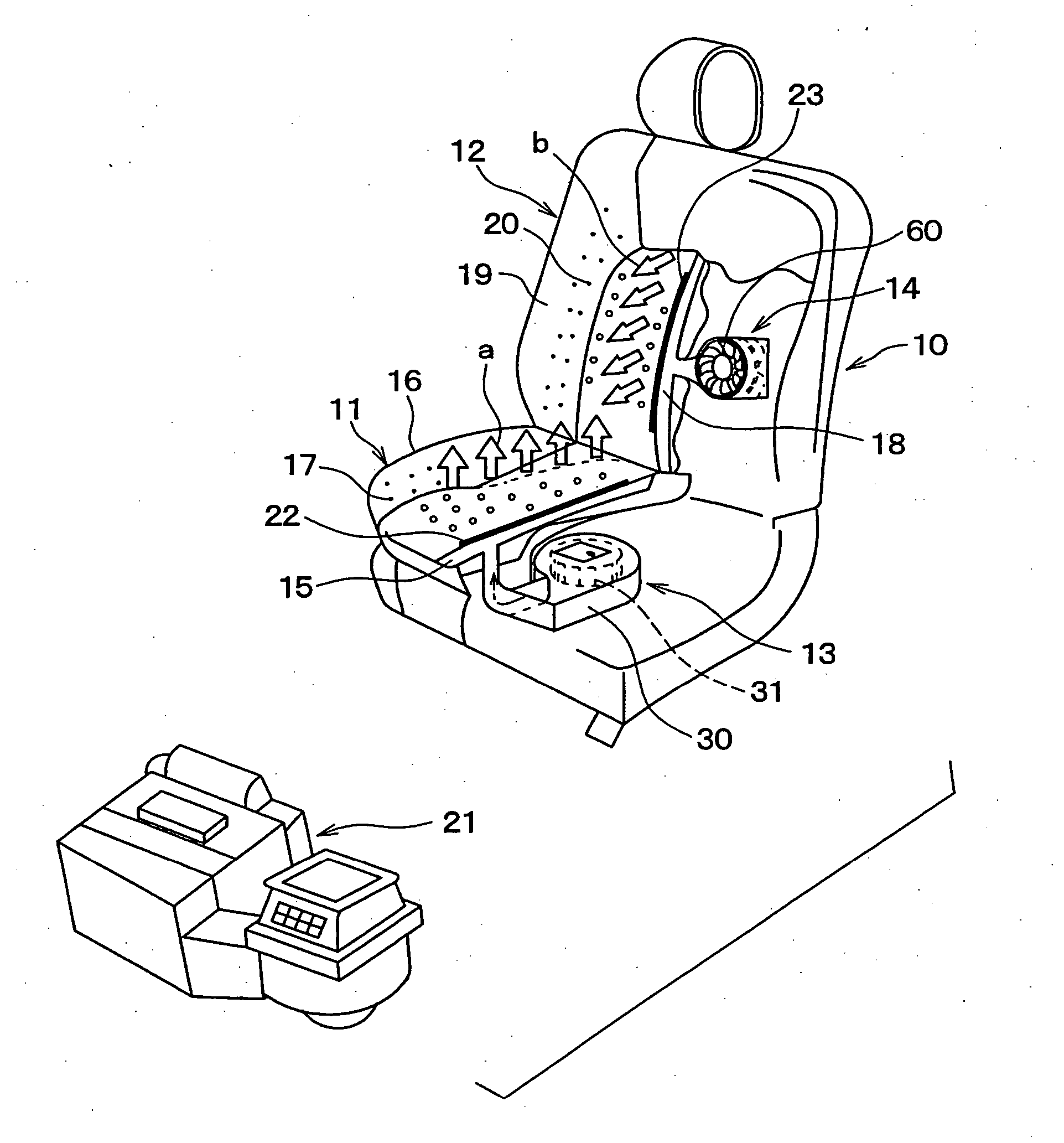
[0027] A seat air conditioner for a vehicle according to a preferred embodiment of the present invention will be described with reference to FIGS. 1-7. The seat air conditioner can be attached to a vehicle seat 10 (e.g., driver seat or front-passenger seat).

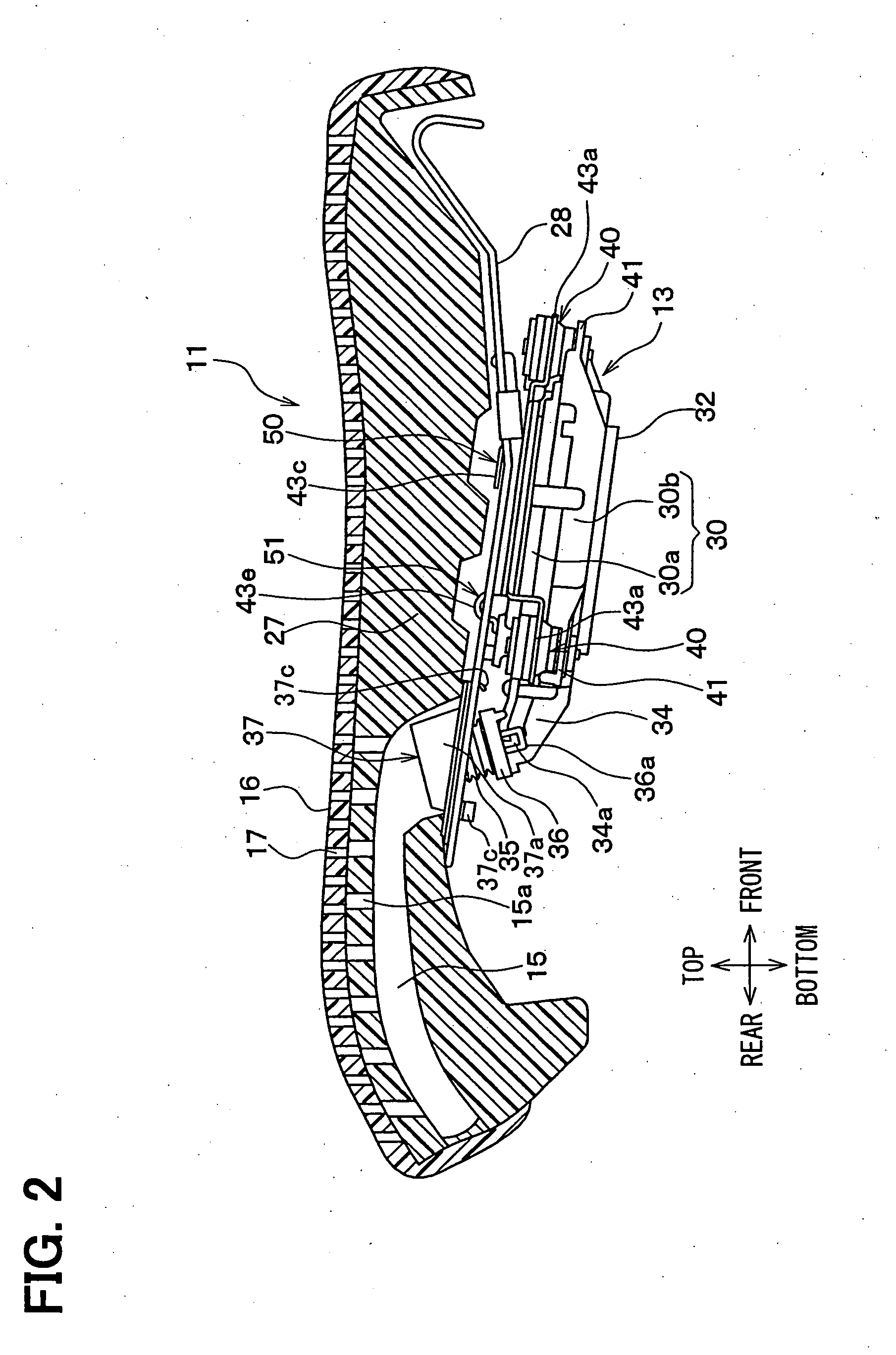
[0028] The seat 10 includes a seat cushion unit 11 contacting the buttocks of a passenger (not shown) seated on the seat 10, and a seat back unit 12 for supporting the back of the passenger. First and second blower units 13, 14 are respectively arranged in the seat cushion unit 11 and the seat back unit 12.

[0029] The first blower unit 13 (blower unit) draws air (inside air) in a passenger compartment of the vehicle from the lower side of the seat cushion unit 11, and blows the inside air having been drawn toward a surface cover member 16 of the seat cushion unit 11 through an air passage 15 formed in the seat cushion unit 11. Thus, as indicated by arrows “a” in FIG. 1, the inside air is discharged toward the...


PUM


Abstract

A seat air conditioner for a vehicle seat includes a blower unit which has a blower fan and an air discharge duct, a vibration isolation unit arranged between the blower unit and a cushion member of the seat, and an accordion duct which is arranged between the air discharge duct and an air passage defined in the cushion member. The blower unit is disposed at an opposite side to the cushion member with respect to seat spring members of the seat. Air blown by the blower fan flows toward a plurality of blowing-out openings formed at a surface cover member of the seat, through the air discharge duct, the accordion duct and the air passage formed in the cushion member.

Description

CROSS REFERENCE TO RELATED APPLICATION [0001] This application is based on a Japanese Patent Application No. 2004-373540 filed on Dec. 24, 2004, the disclosure of which is incorporated herein by reference. FIELD OF THE INVENTION [0002] The present invention relates to a seat air conditioner for a vehicle. BACKGROUND OF THE INVENTION [0003] In a seat air conditioner for a vehicle seat disclosed in US 2004 / 0198212A1, referring to FIG. 8, vibration excited by a blower unit 13 is restricted from being transmitted to the side of the seat. [0004] In this case, the blower unit 13 is arranged at the lower side of seat spring members 28 and 280, which are located at the lower side of a cushion member 27. The seat spring members 28 and 280 are arranged between a cover member 71 of the blower unit 13 and an attachment bracket 70 through resilient damper members 72 and 73, so that the vibration excited by the blower unit 13 is restricted from being transmitted to the side of the cushion member ...

Claims


Application Information

Patent Timeline
Patent Type & Authority Applications(United States)
IPC IPC(8): A47C7/72A47C31/00
CPCB60N2/5635B60N2/5657Y10S454/907B60N2/5642
Inventor AOKI, SHINJI
Owner DENSO CORP
Why Eureka
Try Eureka