Supercharge Your Innovation With Domain-Expert AI Agents!

Device and method for low-power fast-response voltage regulator with improved power supply range

a voltage regulator and fast response technology, applied in the field of integrated circuits, can solve the problems of limiting the operation time of battery-powered devices, the power consumption of voltage regulators in standby mode, and the power consumption of battery-powered devices in standby mode, so as to improve the frequency response of voltage regulators and reduce the power consumption of voltage regulators. , the effect of expanding the supply voltage rang

Active Publication Date: 2006-06-29
SEMICON MFG INT (SHANGHAI) CORP
View PDF2 Cites 5 Cited by
  • Summary
  • Abstract
  • Description
  • Claims
  • Application Information

AI Technical Summary

Benefits of technology

[0017] Many benefits are achieved by way of the present invention over conventional techniques. Some embodiments of the present invention significantly reduce the power consumption of the voltage regulator in the standby mode. Certain embodiments of the present invention significantly improve the frequency response of the voltage regulator. Some embodiments of the present invention expand range of the supply voltage. For example, the voltage regulator can operate with a supply voltage equal to or larger than the desired output voltage. Depending upon the embodiment, one or more of these benefits may be achieved. These and other benefits will be described in more throughout the present specification and more particularly below.

Problems solved by technology

With the voltage divider, the voltage regulator consumes important energy in the standby mode.
The energy consumption in the standby mode limits the operation time of battery-powered devices.
Furthermore, some battery-powered devices require low standby power consumption and cannot rely on the regulator that consumes significant power in the standby mode.
On the other hand, without the voltage divider, the voltage regulator often cannot work with a continuous range of system power supply.

Method used


Image

  • Device and method for low-power fast-response voltage regulator with improved power supply range
  • Device and method for low-power fast-response voltage regulator with improved power supply range
  • Device and method for low-power fast-response voltage regulator with improved power supply range

Examples


Embodiment Construction

[0022] The present invention is directed to integrated circuits. More particularly, the invention provides a device and method for voltage regulator with low standby current. Merely by way of example, the invention has been applied to a battery powered system. But it would be recognized that the invention has a much broader range of applicability.

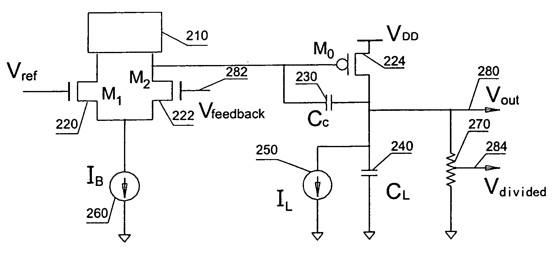
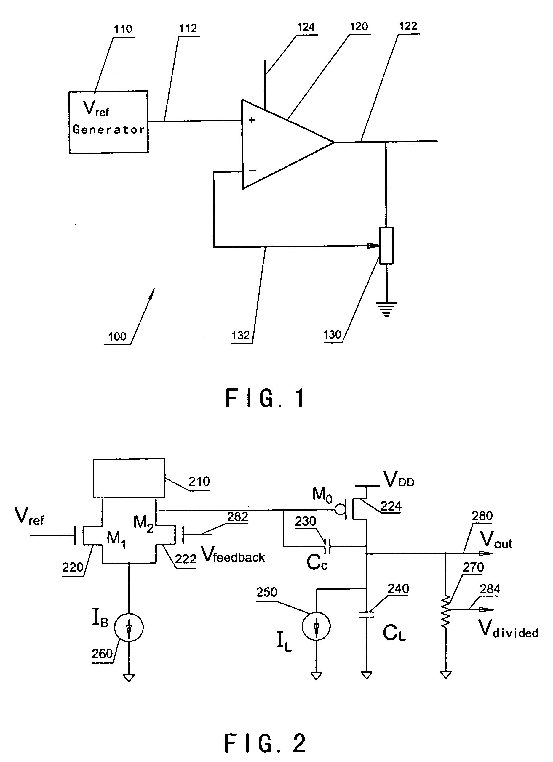
[0023]FIG. 2 is a simplified conventional voltage regulator. The device 200 includes the following components:

[0024] 1. Current Mirror 210;

[0025] 2. Transistors 220, 222 and 224;

[0026] 3. Compensation capacitor 230;

[0027] 4. Load capacitor 240;

[0028] 5. Current supplies 250 and 260;

[0029] 6. Voltage divider 270.

[0030] The current mirror 210, the transistors 220 and 222, and the current supplier 260 form a first stage of a differential amplifier, and the transistors 220 and 222 forms a differential pair. The transistor 224, the compensation capacitor 230, the load capacitor 240, the current supplier 250, and the voltage divider 270 f...


PUM


Abstract

An apparatus and method for regulating voltage levels. The apparatus includes a first transistor and a second transistor coupled to the first transistor. The first transistor is configured to receive a reference voltage, and the second transistor is configured to receive a feedback voltage and generate a first voltage. The first voltage is associated with a difference between the reference voltage and the feedback voltage. Additionally, the apparatus includes a third transistor coupled to the second transistor and configured to receive the first voltage from the second transistor and generate an output voltage in response to at least the first voltage. Moreover, the apparatus includes a fourth transistor coupled to the third transistor and configured to receive the output voltage from the third transistor and generate the feedback voltage, and a first current generation system coupled to the fourth transistor through at least a node.

Description

CROSS-REFERENCES TO RELATED APPLICATIONS [0001] This application claims priority to Chinese Patent Application No. 200410099391.3, filed Dec. 28, 2004, entitled “Device and Method for Low-Power Fast-Response Voltage Regulator with Improved Power Supply Range,” by Inventors Wenzhe Luo and Paul Ouyang, commonly assigned, incorporated by reference herein for all purposes. [0002] The following three commonly-owned co-pending applications, including this one, are being filed concurrently and the other two are hereby incorporated by reference in their entirety for all purposes: [0003] 1. U.S. patent application Ser. No. ______, in the name of Wenzhe Luo, titled, “Device and Method for Voltage Regulator with Low Standby Current,” (Attorney Docket Number 021653-003300US); [0004] 2. U.S. patent application Ser. No. ______, in the name of Wenzhe Luo, titled, “Device and Method for Voltage Regulator with Stable and Fast Response and Low Standby Current,” (Attorney Docket Number 021653-003800US...

Claims


Application Information

Patent Timeline
Patent Type & Authority Applications(United States)
IPC IPC(8): G05F1/40G05F1/618
CPCG05F1/56
Inventor LUO, WENZHEOUYANG, PAUL
Owner SEMICON MFG INT (SHANGHAI) CORP
Features
  • R&D
  • Intellectual Property
  • Life Sciences
  • Materials
  • Tech Scout
  • Unparalleled Data Quality
  • Higher Quality Content
  • 60% Fewer Hallucinations
Learn More