Antenna

a technology of antennas and antennas, applied in the field of antennas, can solve the problems of requiring a larger area for installation, affecting the performance of antennas, so as to achieve enhanced performance, reduce size, and avoid matching and mixing losses.

Inactive Publication Date: 2006-06-29
DX ANTENNA CO LTD
View PDF4 Cites 10 Cited by
  • Summary
  • Abstract
  • Description
  • Claims
  • Application Information

AI Technical Summary

Benefits of technology

[0043] The present invention is mainly advantageous in that it can dispense with a matcher and a mixer and as a result no matching and mixing losses can be caused. The present antenna can thus be reduced in size and also enhanced in performance.
[0044] The present invention is also advantageous in that it can provide a radiator fed through a strip line and the strip line at a transmission line can have an impedance set to be equal to the characteristic impedance of a coaxial cable. Thus the coaxial cable can directly be connected to the strip line.

Problems solved by technology

As such, if the antenna is increased in size, it requires a larger area for installation and is also more susceptible to wind.
In particular, if a Yagi antenna having a reflector increased in area to achieve enhanced performance receives wind, it is susceptible to damage.
Larger antennas, however, tend to cause problems associated with installation area, damage, and the like as described above.
Furthermore, for the stacked antenna shown in FIG. 25, the matchers and the mixers provide losses, and the performance is not improved as theoretically expected.
Furthermore, the above described miniature and omnidirectional antennas do not have performance suitable for receiving digital terrestrial broadcasts.
Thus omnidirectional antennas are susceptible to multipath propagation.
As such, conventional miniature and omnidirectional antennas are unsuitable for receiving digital terrestrial broadcasts.

Method used


Image

  • Antenna
  • Antenna
  • Antenna

Examples


first embodiment

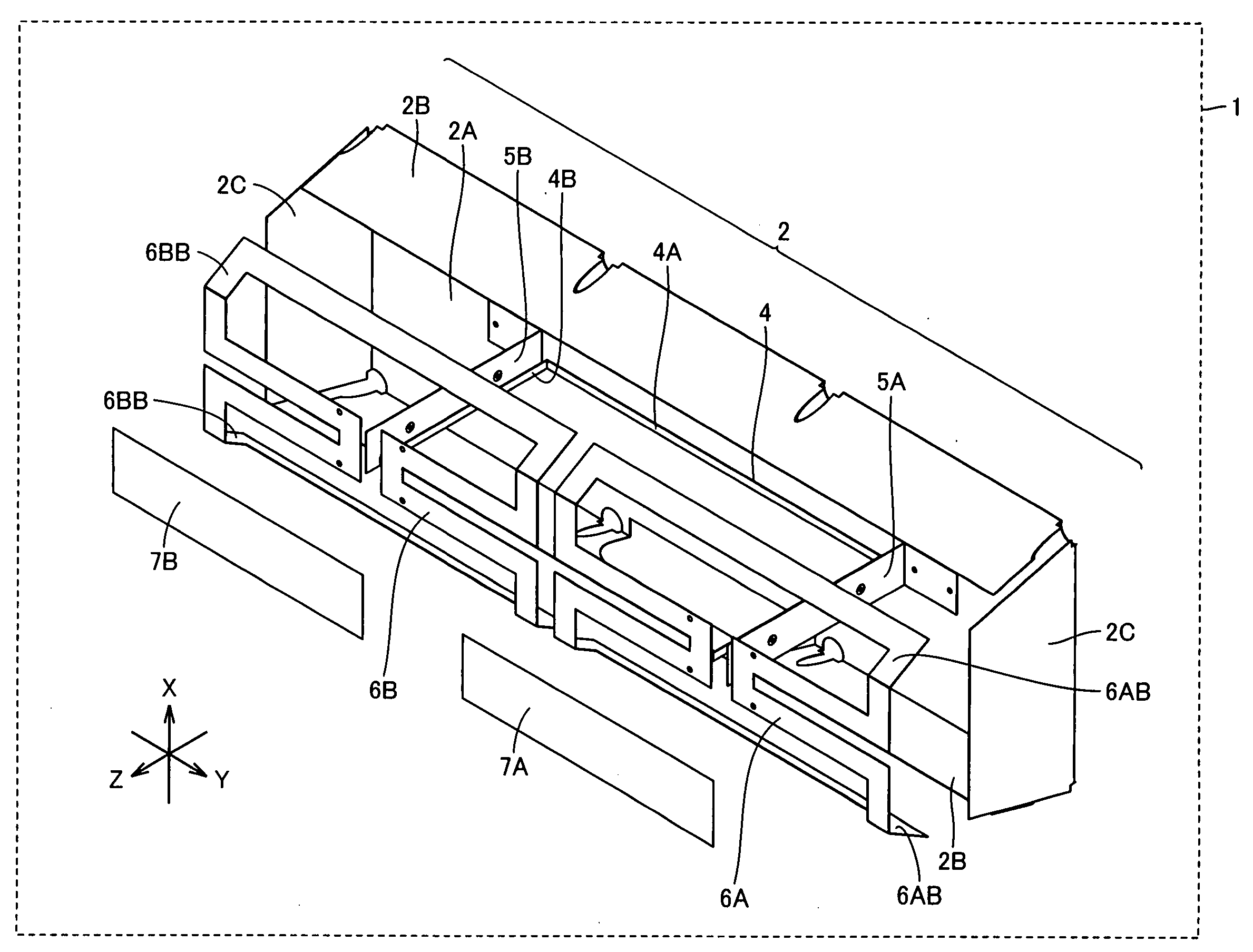
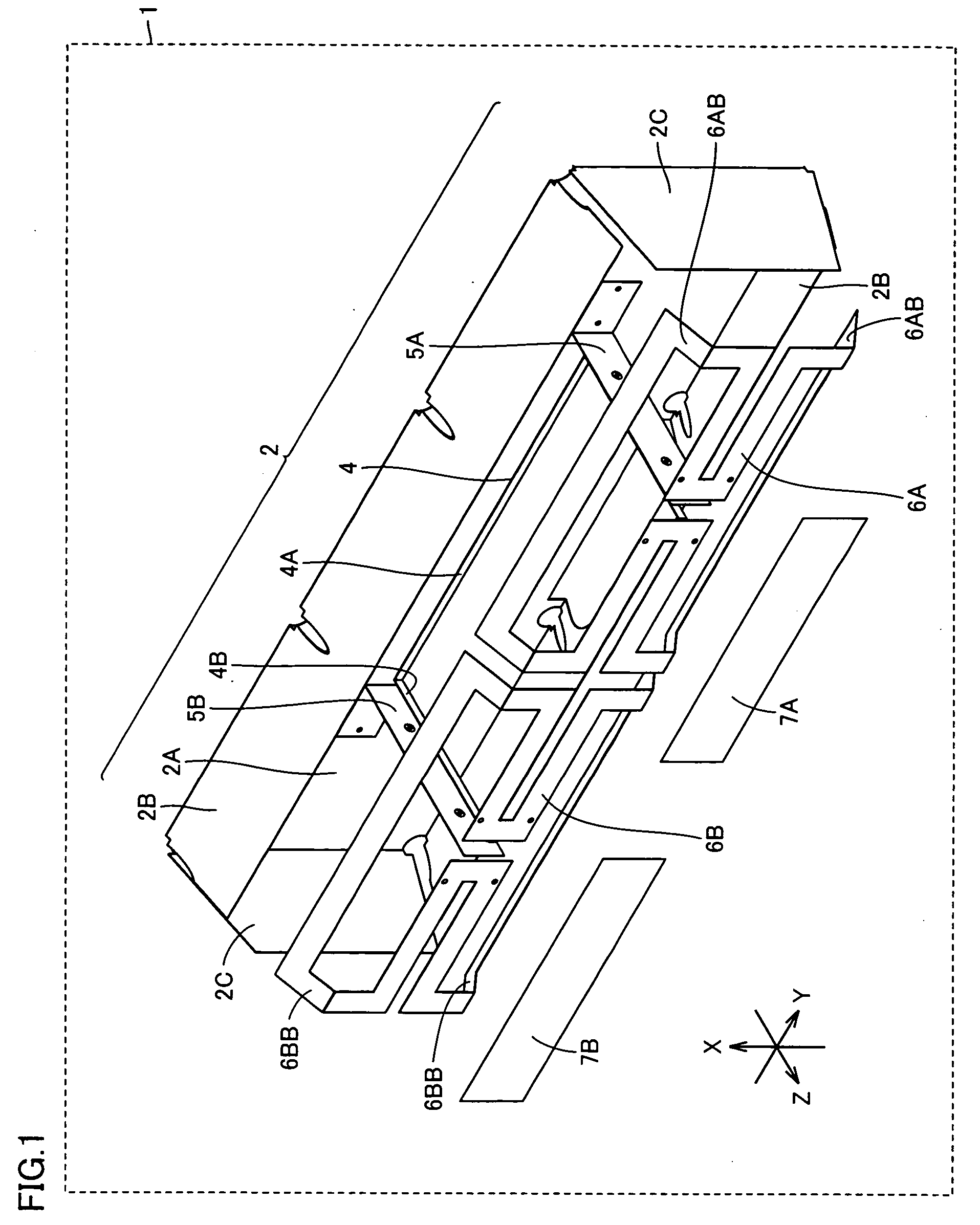
[0069]FIG. 1 is an overall view of the present antenna in a first embodiment.

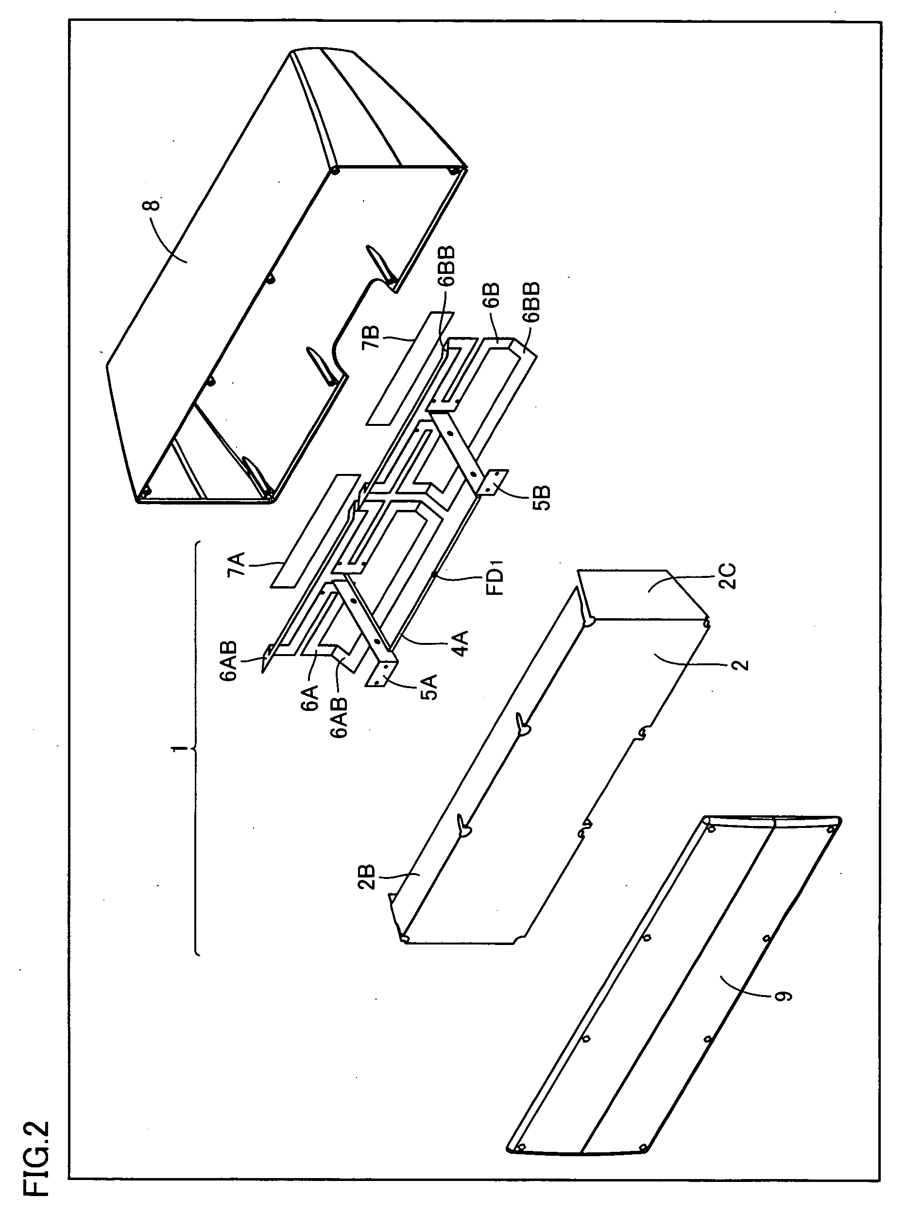
[0070] With reference to the figure, an antenna 1 includes a reflector 2, a transmission line 4, conductive plates 5A and 5B, radiators 6A and 6B, and directors 7A and 7B.

[0071] Reflector 2 includes a flat portion 2A reflecting a UHF band electric wave. Reflector 2 is formed of conductor. Note that reflector 2 includes peripheral portions 2B and 2C surrounding flat portion 2A and each forming a prescribed angle other than 180° relative to flat portion 2A. In other words, reflector 2 is provided to have a periphery bent in a direction of reflection (i.e., in the positive direction along the Z axis). Reflector 2 thus structured allows antenna 1 to be reduced in size.

[0072] Note that while FIG. 1 shows reflector 2 formed to have peripheral portions 2B and 2C both bent in the direction of reflection, reflector 2 may alternatively be formed to have one of peripheral portions 2B and 2C bent in the direction of...

second embodiment

[0136]FIG. 15 shows the present antenna in a second embodiment.

[0137] With reference to the figure, an antenna 1A is similar to antenna 1 except that the former includes directors 7A1 and 7B1 implemented by conductive plates.

[0138] Directors 7A and 7A1 are arranged in parallel and cooperate with flat portion 2A to sandwich radiator 6A associated therewith. Similarly, directors 7B and 7B1 and are arranged in parallel and cooperate with flat portion 2A to sandwich radiator 6B associated therewith. The plurality of directors thus provided allows the antenna to be enhanced in performance. Note that while directors 7A and 7A1 are arranged parallel to radiator 6A and directors 7B and 7B1 are arranged parallel to radiator 6B, directors 7A, 7A1, 7B, 7B1 may be arranged at an appropriate angle relative to each radiator.

[0139]FIG. 16 is the present antenna of the second embodiment in an exemplary variation.

[0140] With reference to the figure, an antenna 1B is similar to antenna 1A of FIG....

third embodiment

[0143]FIG. 17 is an overall view of the present antenna in a third embodiment.

[0144] With reference to the figure, an antenna 1C is similar to antenna 1 of FIG. 1 except that the former includes directors 7A3 and 7B3 instead of directors 7A and 7B.

[0145] Directors 7A3 and 7B3 each have a center and an end having different distances, respectively, from flat portion 2A. In FIG. 17, the distance between the end and flat portion 2A is smaller than that between the center and flat portion 2A. More specifically, directors 7A3 and 7B3 are both in the form of the letter U or an arc as seen in the direction of the Y axis. Directors 7A3 and 7B3 thus formed can have a smaller dimension along the X axis. Antenna 1C can thus have a reduced size.

[0146] Note that directors 7A3 and 7B3 are not limited in geometry to that shown in FIG. 17. Hereinafter an exemplary variation of the third embodiment will be described in connection with the director's geometry.

[0147]FIG. 18 shows director 7A3 of FI...


PUM


Abstract

A transmission line includes transmission lines parallel and perpendicular, respectively, to a flat portion of a reflector, and the parallel transmission line and the flat portion form a first strip line and the perpendicular transmission line and a conductive plate similarly form a second strip line. Radiators and the transmission line have a radiation impedance and a characteristic impedance, respectively, both set at 150 Ω when the antenna's output terminal has a reference impedance of 75 Ω. If the parallel transmission line has a midpoint serving as the output terminal of the antenna this portion's receiving current is divided in two so that an impedance of half that of the strip line can be provided and a coaxial cable can directly be connected to the transmission line. A matcher or a mixer is not included in the antenna, and matching and mixing losses can be prevented.

Description

[0001] This nonprovisional application is based on Japanese Patent Applications Nos. 2004-379963 and 2005-246049 filed with the Japan Patent Office on Dec. 28, 2004 and Aug. 26, 2005, respectively, the entire contents of which are hereby incorporated by reference. BACKGROUND OF THE INVENTION [0002] 1. Field of the Invention [0003] The present invention relates generally to antennas reduced in size and having excellent reception characteristics and in particular to antennas receiving electric waves of ultrahigh frequency (UHF) band. [0004] 2. Description of the Background Art [0005] Conventionally a variety of antennas have been proposed for different applications. In recent years, in particular, a variety of miniature antennas, omnidirectional antennas and the like intended to be installed indoors, mounted in mobile terminals and the like are proposed. [0006] For example Japanese Patent Laying-open No. 2000-13130 discloses an antenna having a plurality of closed loop elements to be ...

Claims


Application Information

Patent Timeline
Patent Type & Authority Applications(United States)
IPC IPC(8): H01Q21/00
CPCH01Q9/26H01Q21/062
Inventor SHIROSAKA, TOSHIAKIFUJISAWA, SHINGO
Owner DX ANTENNA CO LTD
Why Eureka
Try Eureka