Method of computing a hologram

a computing method and hologram technology, applied in the field of computing holograms, can solve the problems of small observer window and computational requirements, and achieve the effect of reducing computational requirements and high quality

Active Publication Date: 2006-06-29
SEEREAL TECHNOLOGIES
View PDF6 Cites 182 Cited by
  • Summary
  • Abstract
  • Description
  • Claims
  • Application Information

AI Technical Summary

Benefits of technology

[0051] It is an object of this invention to reduce the computational requirements of computing a hologram. It is a further object to realize an electro-holographic display for reconstructing video holograms using a SLM with a conventional resolution; the holograms should provide a high quality reconstructed image.

Problems solved by technology

This can be very computationally intensive.
Further, this approach leads to a small observer window if low-resolution SLMs are used.

Method used


Image

  • Method of computing a hologram
  • Method of computing a hologram
  • Method of computing a hologram

Examples


Embodiment Construction

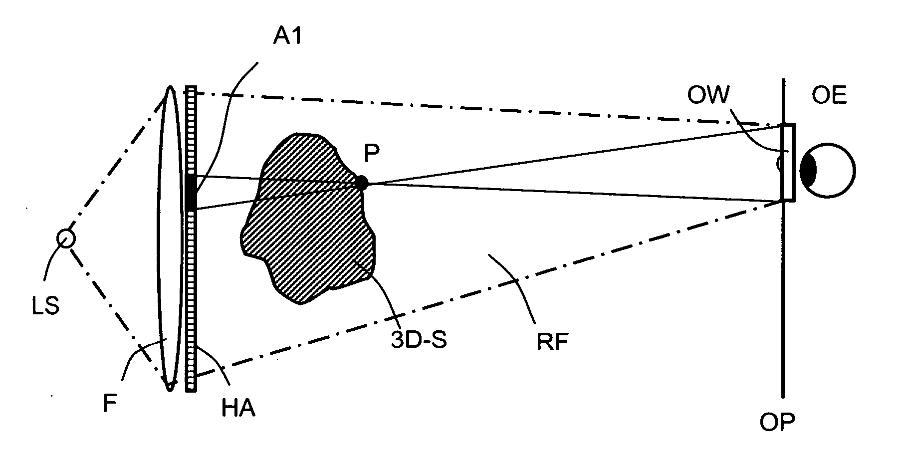
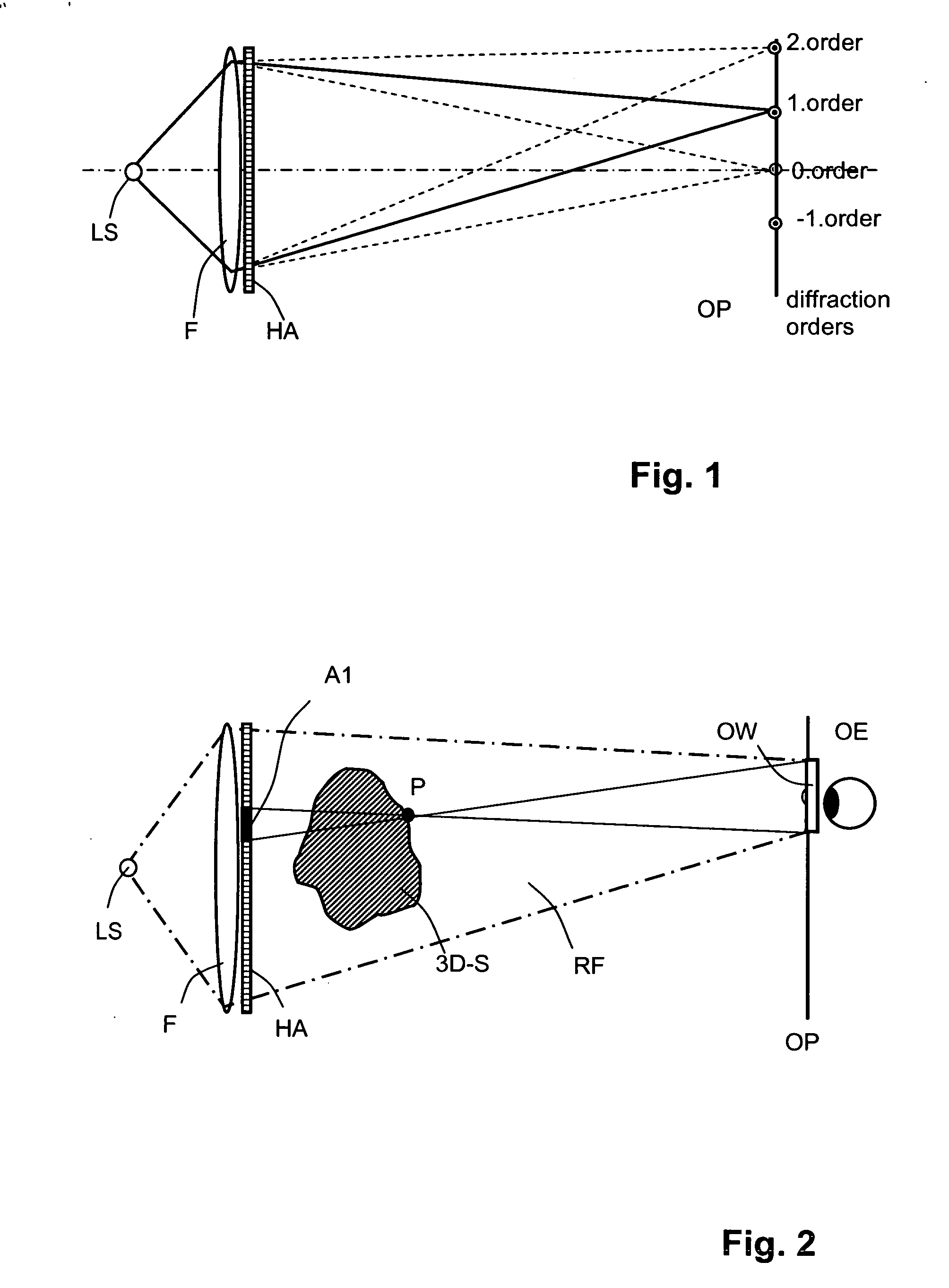
[0082] A device for reconstructing video holograms comprises a SLM (which in this example is a holographic array HA), a sufficiently coherent light source LS and an optical focussing system F. The light source can be realized by virtual illumination means, e.g. a LED array or a line shaped backlight locally controlled and directed by controllable shutter means to form an array of point or line light sources. The holographic array itself consists of pixels which are arranged in a regular pattern; each pixel contains a number of illuminated and transmissive openings (sub-pixels). The openings of each sub-pixel are separately addressable and controllable in phase and / or amplitude to influence the passing illumination light to be encoded via holographic complex valued numbers representing the sequence of a video hologram.

[0083] In the observer plane OP at least one observer window OW is formed in a periodicity interval as a direct or inverse Fourier transform of the video hologram. The...


PUM


Abstract

A method of computing a hologram by determining the wavefronts at the approximate observer eye position that would be generated by a real version of an object to be reconstructed. In normal computer generated holograms, one determines the wavefronts needed to reconstruct an object; this is not done directly in the present invention. Instead, one determines the wavefronts at an observer window that would be generated by a real object located at the same position of the reconstructed object. One can then back-transforms these wavefronts to the hologram to determine how the hologram needs to be encoded to generate these wavefronts. A suitably encoded hologram can then generate a reconstruction of the three-dimensional scene that can be observed by placing one's eyes at the plane of the observer window and looking through the observer window.

Description

BACKGROUND OF THE INVENTION [0001] 1. Field of the Invention [0002] The invention relates to a method of computing a hologram. In particular, it relates to a method of generating holograms using electro-holography. Electro-holography aims at realising computer-generated holograms in real-time (i.e. a reconstructed object can be generated from encoded holographic data in a short space of time). A holographic display typically contains an array of controllable pixels; the pixels reconstruct object points by electronically affecting the amplitude and / or phase of an illuminating light. Such an array is a form of spatial light modulator (SLM). The display may not be array based, but instead be continuous. For example, it may be a continuous SLM, including a continuous SLM with matrix control or an AOM (acousto-optic modulator). [0003] A suitable display device to reconstruct video holograms by spatial amplitude modulation of a light pattern is, for example, a Liquid Crystal Display (LCD)...

Claims


Application Information

Patent Timeline
Patent Type & Authority Applications(United States)
IPC IPC(8): G03H1/08
CPCG03H1/22G03H2001/269G03H2001/0816G03H2001/0858G03H2001/2236G03H2001/2242G03H2001/2263G03H2001/2271G03H2001/303G03H2210/33G03H2210/454G03H2222/34G03H2223/16G03H2225/35G03H2226/02G03H2226/05G03H1/0808G03H2210/30G03H1/0005G03H1/268G03H1/32G03H2001/0088G03H1/2294G03H1/04
Inventor LEISTER, NORBERTHAUSSLER, RALFSCHWERDTNER, ARMIN
Owner SEEREAL TECHNOLOGIES
Why Eureka
Try Eureka