Optical disk apparatus

Inactive Publication Date: 2006-06-29
HITACHI LTD
View PDF6 Cites 16 Cited by
  • Summary
  • Abstract
  • Description
  • Claims
  • Application Information

AI Technical Summary

Benefits of technology

[0009] Accordingly, it is an objective of the invention to provide an optical disk apparatus in which, in the case when the apparatus is shifted from the stopped mode to the intermittent operation at the time of starting the recording operation, when the standby mode is judged not to be necessary, the apparatus is made in the standby mode immediately after the end of the judgment about the necessity of the learning operation, while when the learning operation is judged to be necessary, the apparatus is made in the standby mode after the end of the learning operation, so that the power consumption can be reduced.

Problems solved by technology

On the other hand, the optical disk apparatus is easily affected by the temperature distribution and the surface condition of the optical disk, and thus it is not simple to perform suitable control for the recording and reproduction.
When the intermittent operation is started, the spindle motor, spindle motor control circuit, optical head portion and optical head control circuit are actuated so that the apparatus is made in the operating mode, but after the end of the judgment about the necessity of the learning operation, the operating mode is maintained until the amount of data accumulated in the buffer memory reaches a first predetermined value, thus unnecessary power being consumed.
In addition, even when the learning operation is performed because of a temperature difference between the current temperature and the temperature previously measured at the past learning operation time, the intermittent operation is started and the elements of spindle motor, spindle motor control circuit, optical head portion and optical head control circuit are actuated so that the apparatus is made in the operating mode, but even after the end of the learning operation following the judgment about the necessity of the learning operation, the operating mode is maintained until the amount of data accumulated in the buffer memory reaches the first predetermined amount so that the recording operation is started, thus unnecessary power being consumed.
Here, particularly when the recording time necessary for each round of shooting is short as in the use of a video camera, the unnecessary power consumption in the operating mode continued from the start of the intermittent operation occupies a very large portion of the whole power consumed over all the recording times, thus causing a problem.

Method used


Image

  • Optical disk apparatus
  • Optical disk apparatus
  • Optical disk apparatus

Examples


embodiment 1

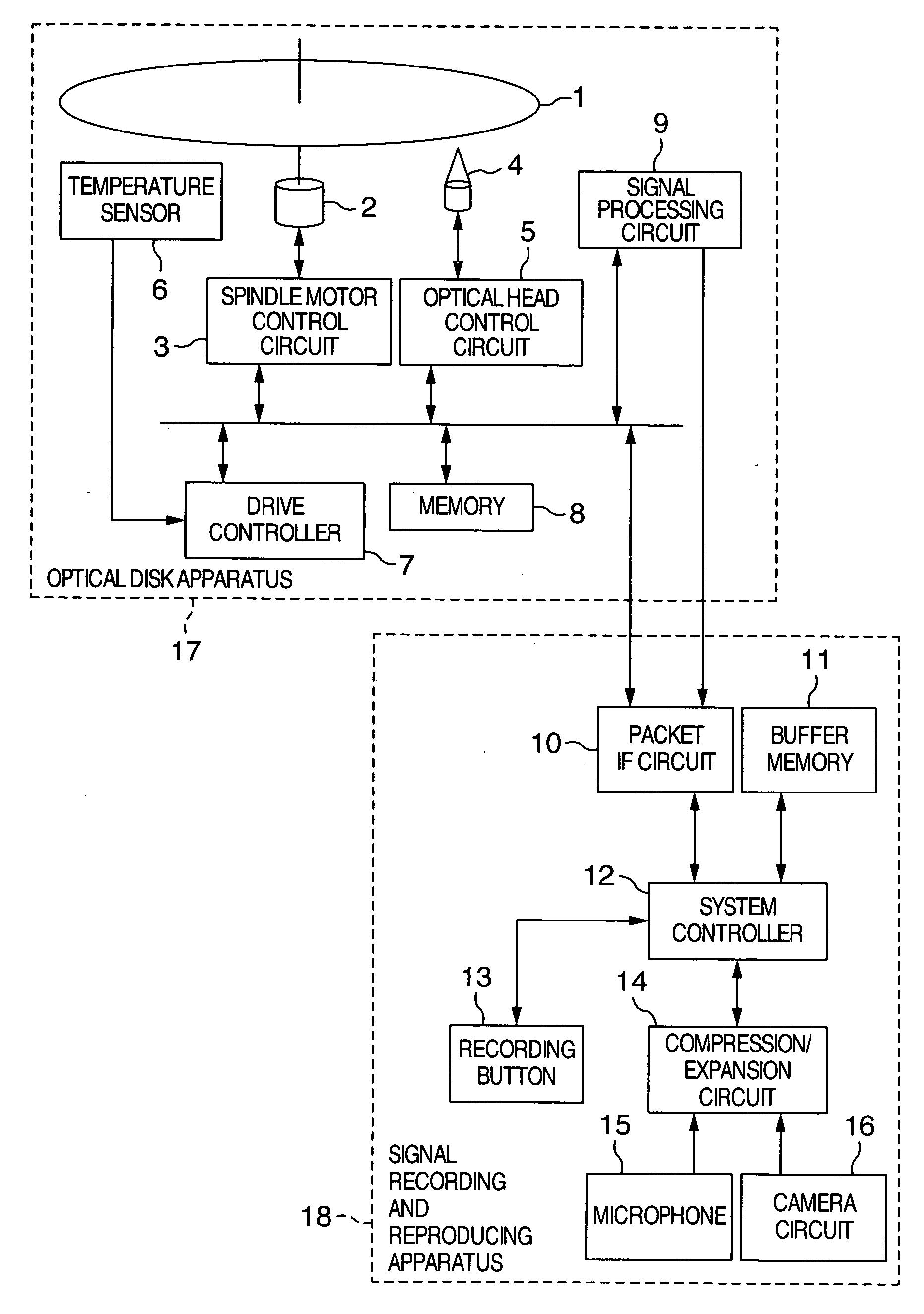
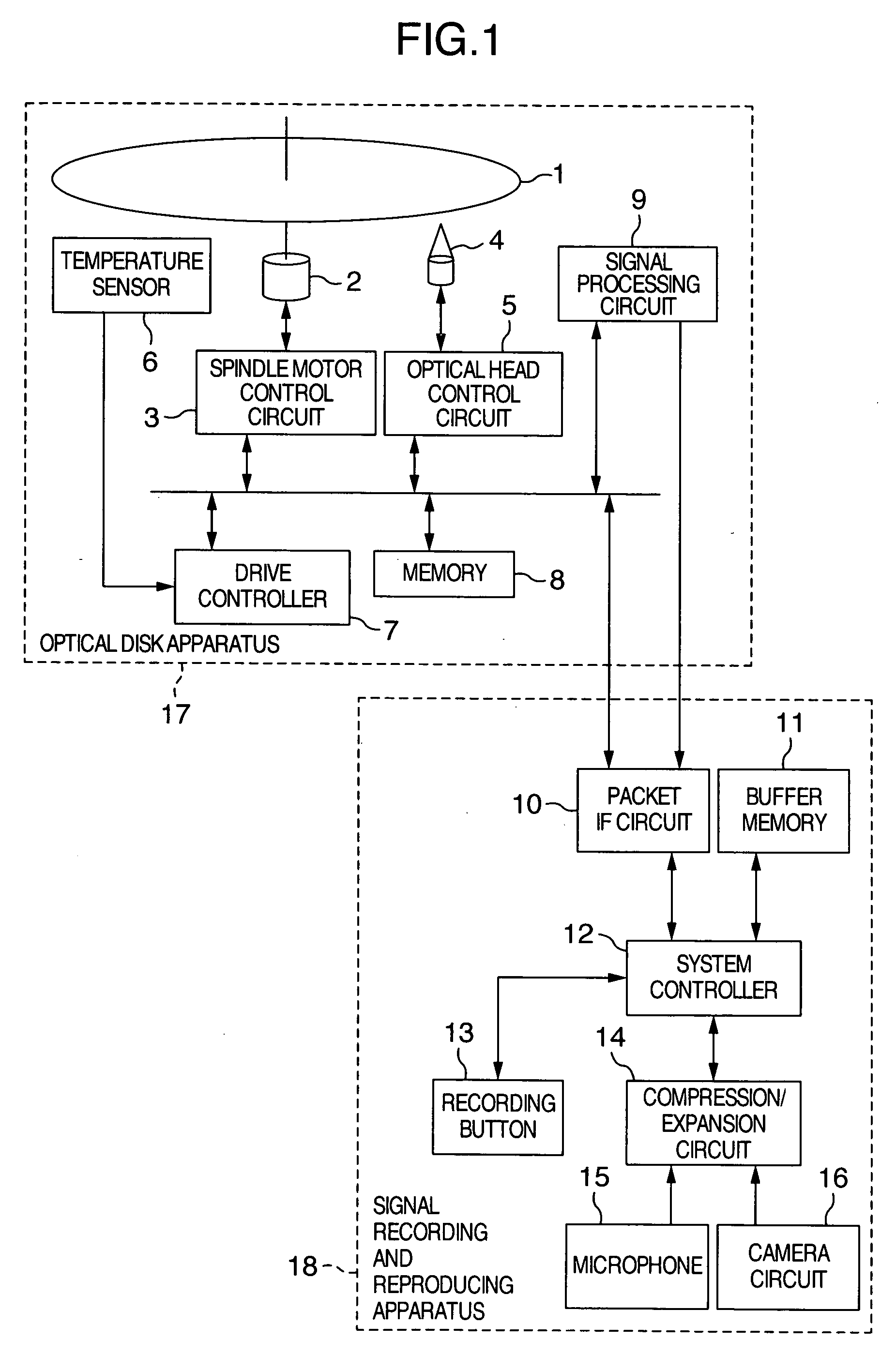
[0024]FIG. 1 is a block diagram showing the construction of the embodiment 1 of a video camera to which the optical disk apparatus of the invention is applied. Referring to FIG. 1, there are shown an optical disk 1, a spindle motor 2, a spindle motor control circuit 3, an optical head portion 4, an optical head control circuit 5, a temperature sensor 6, a drive controller 7, a memory 8, signal processing circuit 9, a packet interface (IF) circuit 10, a buffer memory 11, a system controller 12, a recording button 13, a compression / expansion circuit 14, a microphone 15, and a camera circuit 16. The elements 1 through 9 constitute an optical disk apparatus 17, and the elements 10 through 16 constitute a signal recording and reproducing apparatus 18.

[0025] The spindle motor 2 is controlled by the spindle motor control circuit 3 so that the optical disk 1 can be rotated at a predetermined rotational speed. The optical head portion 4 is constructed to be movable in the focusing and track...

embodiment 2

[0039] The embodiment 2 will be described. The optical disk apparatus 17 and signal recording and reproducing apparatus 18 in the embodiment 2 have the same constructions as those in the embodiment 1, and the recording method using the intermittent operation is the same as in the embodiment 1.

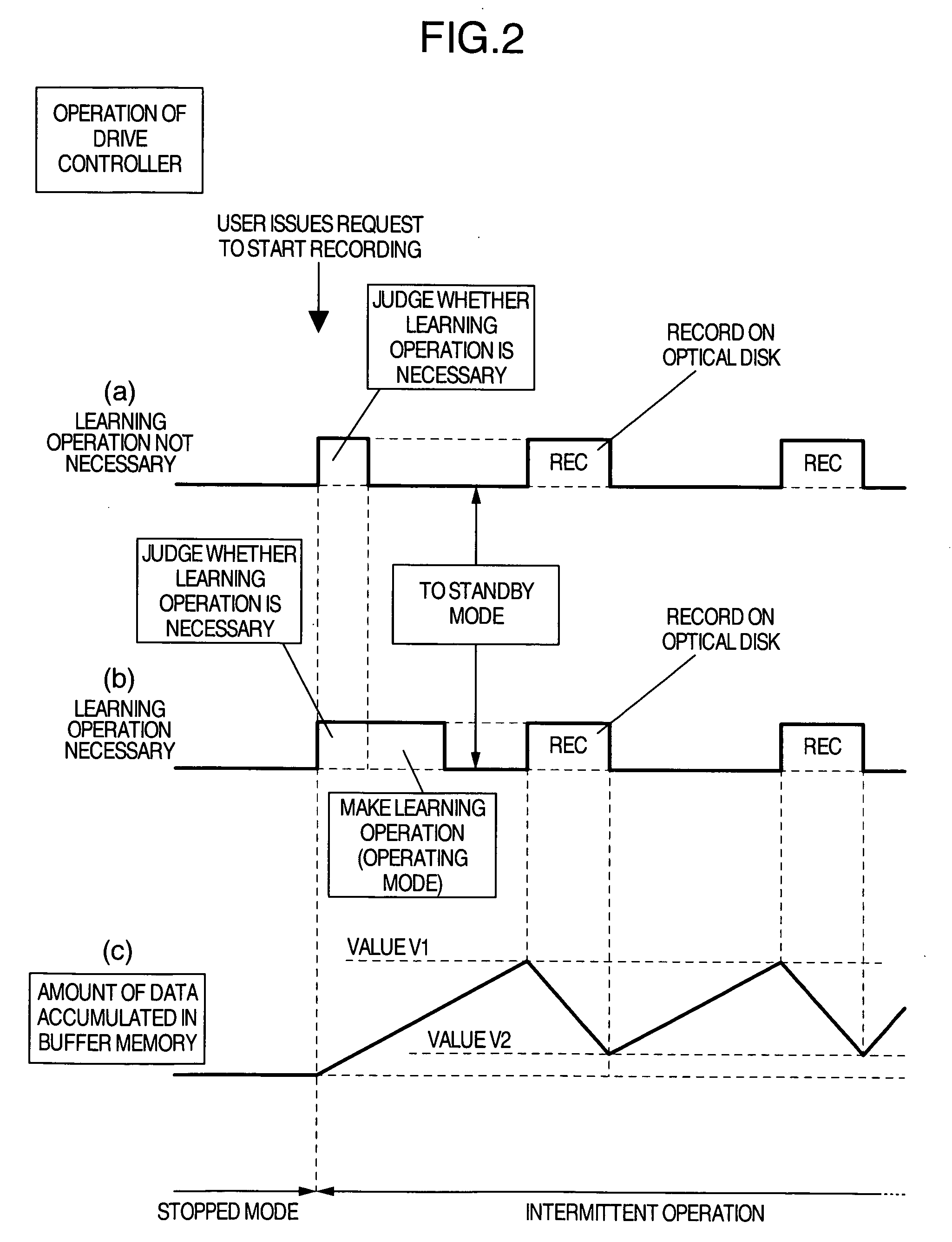
[0040] With reference to FIG. 4, description will be made of the detailed operation of the drive controller 7 in the case when the user enters the request to start recording so that the optical disk apparatus 17 can be shifted from the stopped mode to the intermittent operation. FIG. 4 is a timing chart of the operation of drive controller 7 in the embodiment 2 of the invention. In FIG. 4, the waveform (a) shows the timing of the operation of drive controller 7 in the case where the learning operation is not necessary, the waveform (b) the change of the amount of the digital data accumulated in the buffer memory 11 in the case of the waveform (a) of FIG. 4, the waveform (c) the timing of the o...

embodiment 3

[0045] The embodiment 3 will be described below. The optical disk apparatus 17 and signal recording and reproducing apparatus 18 in the embodiment 3 are the same as in the embodiment 1, and the recording method using the intermittent operation is also the same as in the embodiment 1. However, in this embodiment, the judgment about the necessity of the learning operation is not performed by using the information of the condition of optical disk 1, but made by using only the information of the temperature change.

[0046] With reference to FIG. 5, description will be made of the details of the operation of drive controller 7 in the case where the optical disk apparatus 17 is shifted from the stopped mode to the intermittent operation when the user enters the recording start request. FIG. 5 is a timing chart of the operation of drive controller 7 in the third embodiment according to the invention. In FIG. 5, a waveform (a) shows the timing of the operation of drive controller 7 in the ca...


PUM


Abstract

An optical disk apparatus includes an intermittent operation unit that causes a recording / standby memory device to accumulate an audio signal and video signal to be recorded and to intermittently read the signals, and causes a spindle motor control circuit and optical head control circuit to be intermittently actuated in response to the signals so that the signals can be recorded on an optical disk, a learning operation unit that obtains control values suited to the spindle motor control circuit and optical head control circuit, and a unit that judges about the necessity of the learning operation according to a temperature change and a surface condition of the optical disk.

Description

[0001] The present application claims priority from Japanese application JP2004-372539 filed on Dec. 24, 2004, the content of which is hereby incorporated by reference into this application. BACKGROUND OF THE INVENTION [0002] The present invention relates to optical disk apparatus that make intermittent recording operation and that can make learning operation in association with the recording operation, and particularly to the technology for reducing power consumption by stopping unnecessary operations when the recording is started. [0003] In recent years, we often see recording / reproducing apparatus that use large-capacity optical disks as recording media. The typical examples of these apparatus are video cameras and video recorders. In the optical disk apparatus that are used in these video cameras, it is important subject to reduce the power consumption. Particularly, the portable apparatus such as video cameras are generally driven by batteries. In order that the video camera ca...

Claims


Application Information

Patent Timeline
IPC IPC(8): G11B5/09
CPCG11B19/02
Inventor KAZAMI, YUSUKEUEMURA, KAZUNORIMINABE, KOUJI
Owner HITACHI LTD
Why Eureka
Try Eureka