Optical pluggable transceiver

a technology of optical transceivers and plug-ins, which is applied in the direction of optical elements, instruments, optics, etc., can solve the problems of increasing the cost of components and assembly, limiting the area where the components may be mounted, and reducing the heat dissipation function of components installed on the substrate, so as to reduce the process cost, facilitate assembly and disassembly, the effect of enhancing heat dissipation performan

Active Publication Date: 2006-06-29
SUMITOMO ELECTRIC IND LTD
View PDF5 Cites 28 Cited by
  • Summary
  • Abstract
  • Description
  • Claims
  • Application Information

AI Technical Summary

Benefits of technology

[0013] In the transceiver thus assembled, the metal heat dissipating member comes in contact to the electronic circuit on the substrate in direct, or via a thermal sheet. Besides, the surface opposite to the surface touching the electronic circuit exposes outward in the greater part thereof, accordingly, the heat dissipating performance may be enhanced.
[0014] Moreover, the present transceiver assembles the OSA, the substrate, and the heat dissipating member with the frame only by fitting without any screwing or gluing. Respective members provide structures easy to assemble and hard to disassemble to each other. Accordingly, the reduction of the process cost not only due to decreasing the number of the component used in the assembly but also simplifying the process.

Problems solved by technology

However, this MSA merely specifies the fundamental electrical specification, the pin-assigning, and the physical dimensions, rules no substantial architecture.
Although the resin made chassis reduces the cost or the price of the transceiver, the heat dissipating function for components installed on the substrate might have disadvantages because the resin made chassis fixes the substrate so as to wrap the substrate.
Moreover, the width of the chassis limits the width of the substrate, which also limits the area where the components may be mounted.
The fixing member increases the number of components which increases the cost not only in the components themselves but also the assembly thereof.
However, the die-casting requires the post processing for protecting the die-cast metal from deteriorating, which may increase the process cost.
Thus, the conventional transceiver is inconsistent in the heat dissipating function and the production cost.
The transceiver, whose dimensions are ruled by the agreement, is also inconsistent in the area capable of mounting the components and simplifying the manufacturing.

Method used


Image

  • Optical pluggable transceiver
  • Optical pluggable transceiver
  • Optical pluggable transceiver

Examples


Embodiment Construction

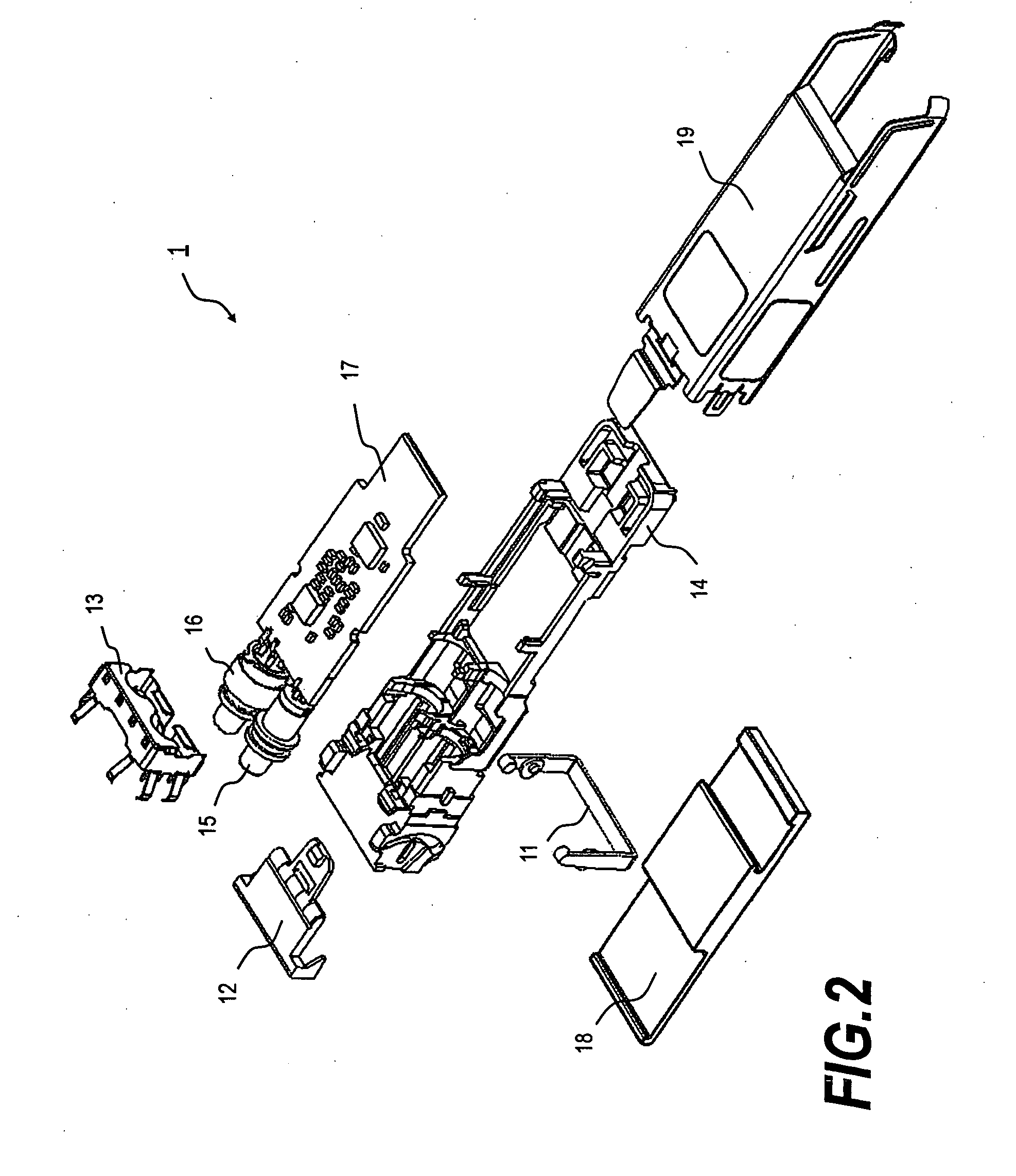
[0032] Next, preferred embodiments of the optical transceiver according to the present invention will be described as referring to accompanying drawings. In the drawings and the explanations, the same symbols and the same numerals will refer the same elements without overlapping explanations. The present invention provides an optical transceiver, which solves the subjects not only to maintain the heat dissipating performance and ensure the widest area for mounting the components but also to reduce the number of the components as reducing the cost themselves, in addition to simplify the assembly of the components, accordingly, to decrease the production const thereof.

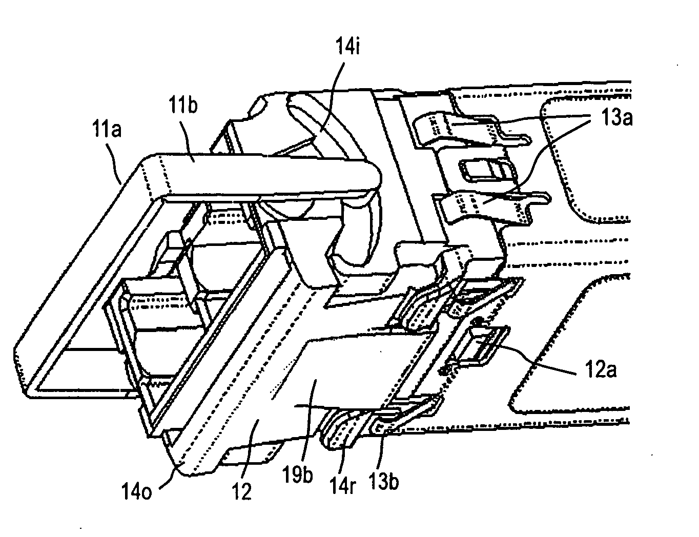
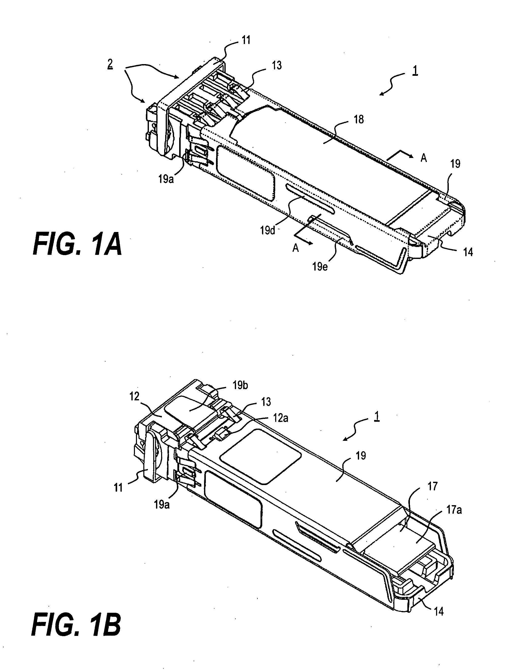
[0033]FIG. 1A is a perspective diagram of the transceiver 1 viewed from the top thereof, while FIG. 2A is a diagram viewed from the bottom. The optical transceiver 1 has a rectangular parallelepiped shape, the forward end of which forms an optical receptacle 1a, while the rear end forms an electrical plug 17a, which mat...


PUM


Abstract

The optical pluggable transceiver according to the present invention has features of a good heat dissipating function with a simplified configuration thereby reducing the cost of not only the component used but also the process itself. The transceiver of the present invention comprises a resin frame, an optical subassembly, a electronic substrate, both mounted on the frame, a heat dissipating member, made of metal, for conducting and radiating heat generated by the electronic circuit on the substrate, and a metal cover for putting these frame, subassembly, substrate, and heat dissipating member therein. A greater part of the surface of the heat dissipating member exposes from the cover, accordingly, the efficiency for radiating heat may be improved. Moreover, these members of the frame, the optical subassembly, the substrate, the heat dissipating member, and the cover are assembled only by fitting without screwing or gluing. Accordingly, the manufacturing process of the transceiver can be extremely simplified.

Description

CROSS REFERENCE TO RELATED APPLICATIONS [0001] The present application claims the benefit of the provisional application Ser. No. 60 / 622,690, filed Oct. 28, 2004; and the provisional application Ser. No. 60 / 622,802, filed Oct. 29, 2004.BACKGROUND OF THE INVENTION [0002] 1. Field of the Invention [0003] The present invention relates to a structure of a pluggable optical transceiver, in particular, the invention relates to a new structure of the transceiver which enables to reduce the cost of the production thereof. [0004] 2. Related Prior Art [0005] The pluggable optical transceiver (hereinafter denoted as transceiver) is installed on the host system such that a cage, which is made of metal and has a box shape with one end being opened and protruded from the face panel of the host system, receives the transceiver in the open end thereof to expose the optical receptacle provided in the front end of the transceiver from the face panel of the host system. The optical receptacle receives...

Claims


Application Information

Patent Timeline
Patent Type & Authority Applications(United States)
IPC IPC(8): G02B6/36
CPCG02B6/4201G02B6/4292G02B6/4245G02B6/4256G02B6/4261G02B6/4266G02B6/428
Inventor MIZUE, TOSHIOKURASHIMA, HIROMI
Owner SUMITOMO ELECTRIC IND LTD
Why Eureka
Try Eureka