High performance, high efficiency fiber optic link for analog and RF systems

a fiber optic link, high efficiency technology, applied in the field of fiber optic communication systems, can solve the problems of inability to transmit high power, high insertion loss, and significant performance shortfall of fiber optic links, and achieve low insertion loss and power consumption, high efficiency, and high performance.

Inactive Publication Date: 2006-06-29
ARTISAN LAB CORP
View PDF19 Cites 33 Cited by
  • Summary
  • Abstract
  • Description
  • Claims
  • Application Information

AI Technical Summary

Benefits of technology

[0010] The present invention relates generally to a high performance, high efficiency fiber optic system for distributing analog and RF communications. The system of the present invention utilizes pulse width modulation (PWM) to distribute analog and RF communications with relatively low insertion loss and power consumption while maintaining acceptable dynamic range, improving power added efficiency and overall low operating costs. The system of the present invention function

Problems solved by technology

However, these fiber optic links have significant performance shortfalls such as high insertion loss, inability to transmit high power, limited dynamic range and high power consumption.
Space and airborne systems such as unmanned aerial vehicles (UAV), tethered satellites, decoys and space based radar have limited available prime power and required reduced weight and power consumption while the demand for transmission capacity increases.
Fiber optics designed to transmit analog signals exhibit problems including high insertion loss, limited dynamic range, high DC power consumption, and low power added efficiency.
Current high frequency analog optical components contribute to these performance problems.
Also, they are typically cost prohibitive and must adhere to strict linear performance requirements.
Such high optical power is generally in the range of about 22

Method used


Image

  • High performance, high efficiency fiber optic link for analog and RF systems
  • High performance, high efficiency fiber optic link for analog and RF systems
  • High performance, high efficiency fiber optic link for analog and RF systems

Examples


Embodiment Construction

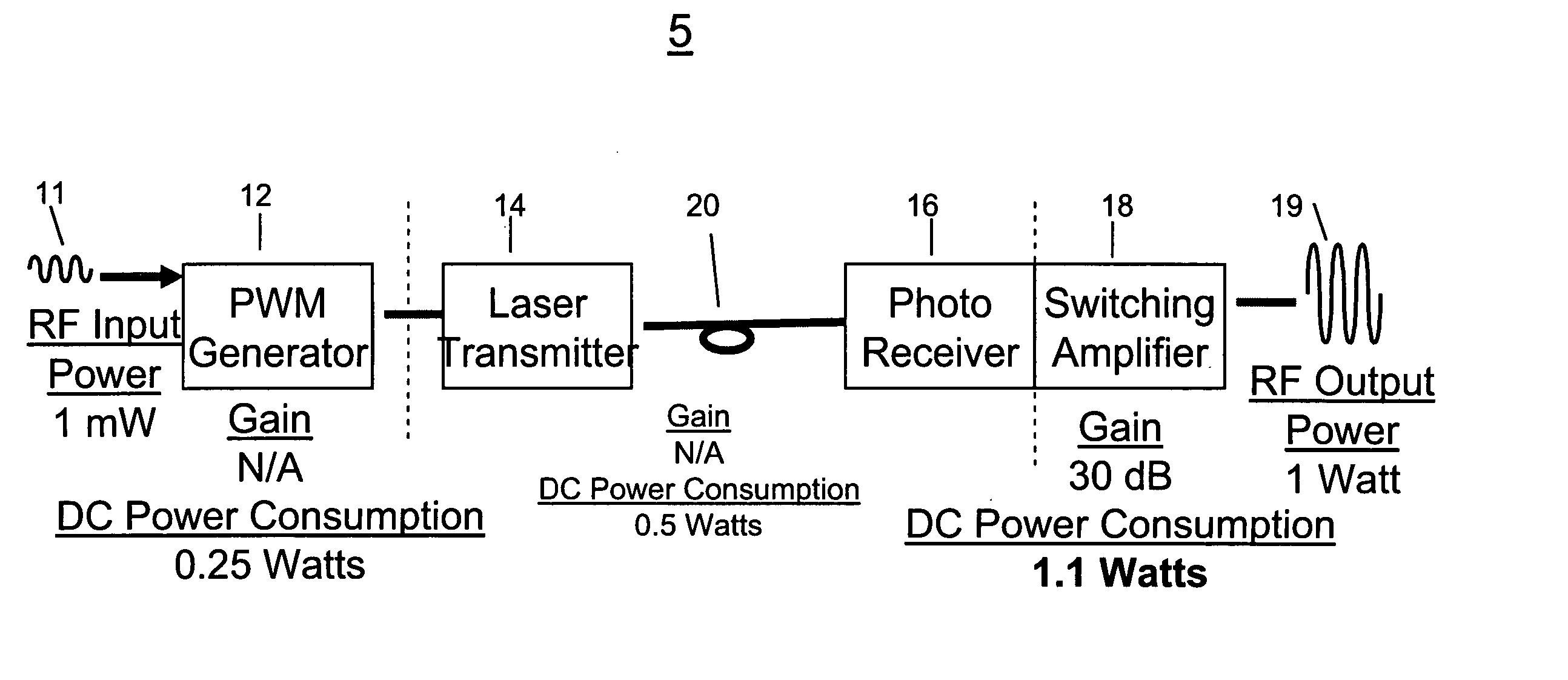
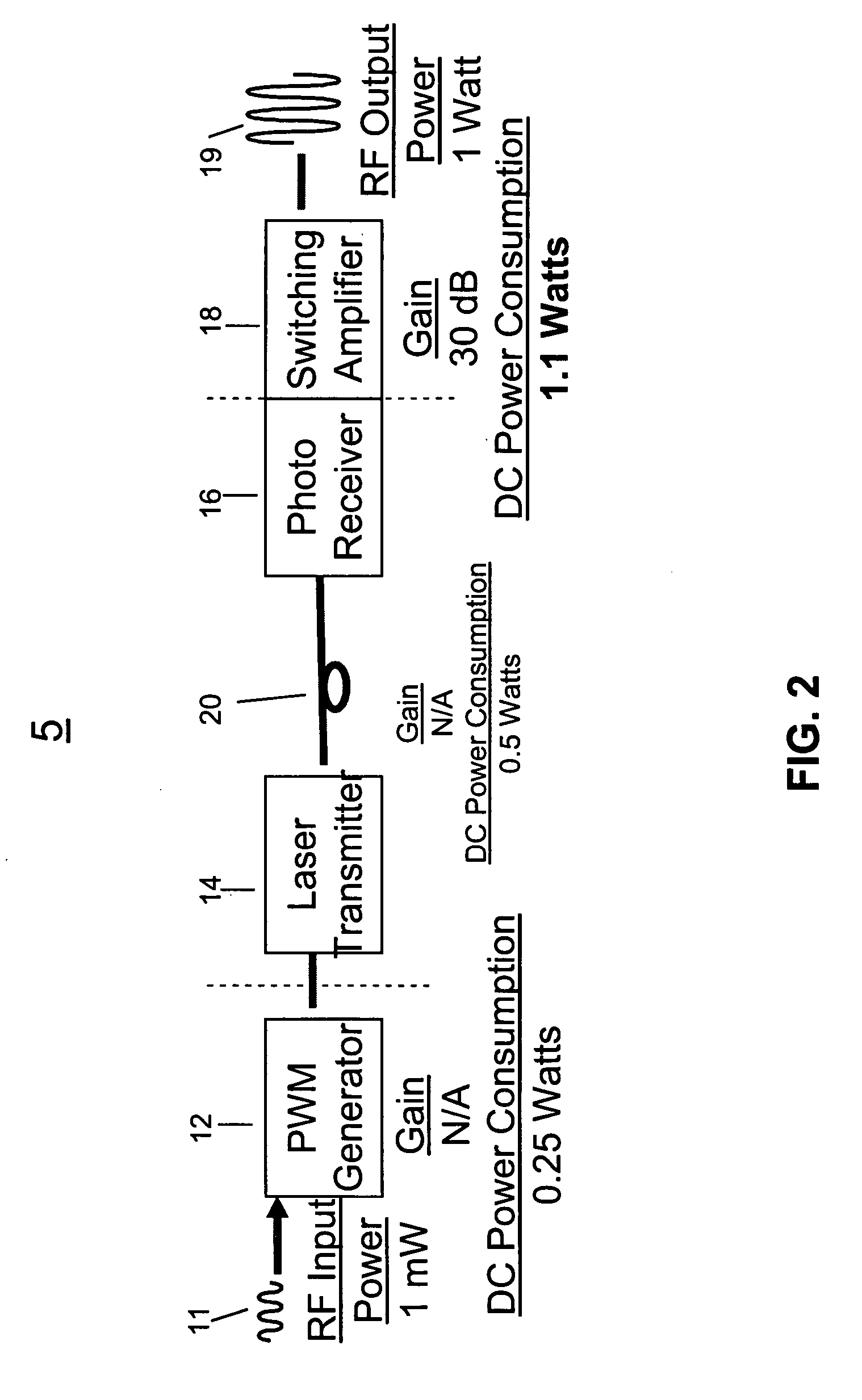
[0039] The present invention is directed to a fiber optic link 3 or communication system which exhibits improved performance including reduced RF insertion loss and reduced DC power consumption. The fiber optic link system of the present invention, as shown in FIG. 2, generally includes a pulse width modulation generator 12, a laser transmitter 14, a photoreceiver 16 with a switching amplifier 18, and a fiber optic cable 20 between the laser transmitter 14 and the photoreceiver 16. The system of the present invention is capable of resolving problems typically associated with fiber optics including limited power transmission, high insertion loss, high power consumption and limited dynamic range, while maintaining a relatively simple design and configuration.

[0040] The fiber optic link system 5 can be utilized in a range of applications including, but not limited to, space systems such as transmission of power from space, signal distribution in antennas, and tethered satellites, UAVs...


PUM


Abstract

A fiber optic link is provided that is receptive of an AM RF input signal, includes an analog comparator for comparing the input signal with a triangle waveform to convert the input signal to a PWM signal. The PWM signal is converted into an optical signal, and transmitted over a fiber optic cable to an optical receiver. The optical receiver converts the optical signal back into a PWM signal, which is amplified via a Class D amplifier. The amplified PWM signal is passed through a low pass filter for converting it into an AM RF output signal having a predetermined power level, the output signal corresponding to the AM RF input signal.

Description

GOVERNMENT INTEREST [0001] This invention was made with Government support under Contract NRO003-03-C-0301 awarded by the NRO (National Reconnaissance Office). The Government has certain rights in this invention.FIELD OF THE INVENTION [0002] The present invention relates generally to communication and radar systems, and more particularly to fiber optic communication systems. BACKGROUND OF THE INVENTION [0003] Analog fiber optic links are being deployed in many military and commercial systems for distributing video, radio-frequency, microwave, and millimeter wave signals. Fiber transmission of analog signals is attractive due to design simplicity, wide bandwidth, small size, light weight, immunity to electromagnetic interference, low data loss, and the cost efficiency of fiber optic cables. However, these fiber optic links have significant performance shortfalls such as high insertion loss, inability to transmit high power, limited dynamic range and high power consumption. Proposed t...

Claims


Application Information

Patent Timeline
IPC IPC(8): H04B10/04
CPCH03F3/08H03F3/217H03F2200/351H04B10/25751
Inventor PAOLELLA, ARTHUR C.
Owner ARTISAN LAB CORP
Why Eureka
Try Eureka