
SiC/SiC composites incorporating uncoated fibers to improve interlaminar strength

a composite material and fiber technology, applied in the field of composite materials incorporating uncoated fibers to improve interlaminar strength, can solve the problems of fiber coating, significant local interlaminar stress, and varying local stresses of turbine components, and achieve the effects of reducing costs, increasing performance, and increasing the performance of aircraft gas turbine engines

Active Publication Date: 2006-06-29
GENERAL ELECTRIC CO
View PDF18 Cites 14 Cited by
  • Summary
  • Abstract
  • Description
  • Claims
  • Application Information

AI Technical Summary

Benefits of technology

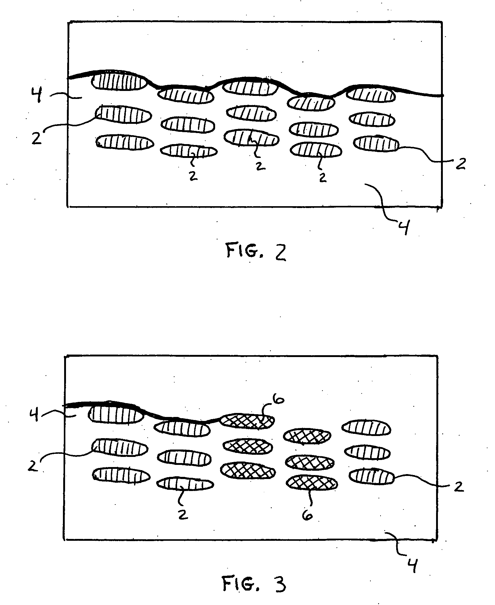
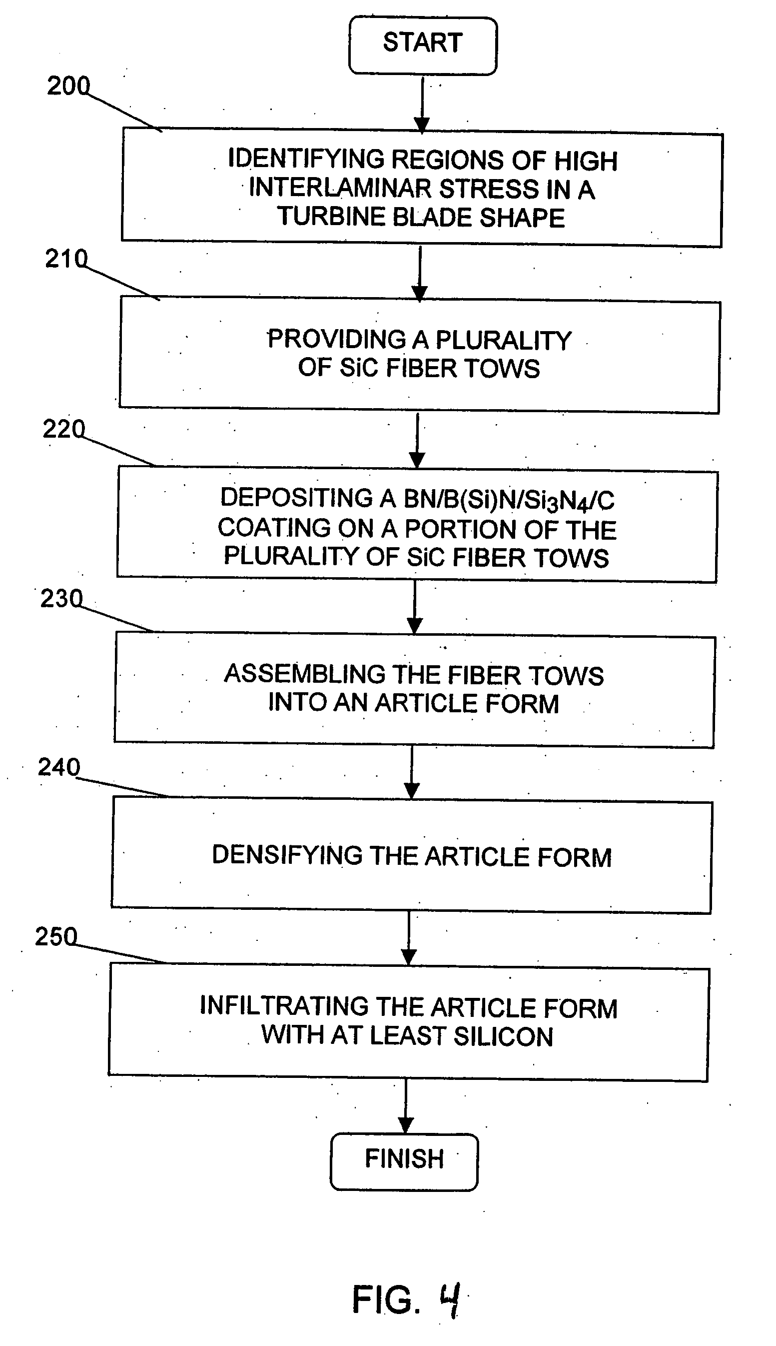
"The present invention is a novel method for manufacturing a turbine engine component made from a ceramic matrix composite (CMC) using both coated and uncoated ceramic fibers. The invention produces a component that has higher interlaminar strength within discrete higher interlaminar stress regions within the component during normal engine operation, thereby improving the functionality of the component. The method involves providing a plurality of unidirectional ceramic fiber tows, applying a coating to a portion of the fiber tows to form coated fiber tows, and laying up the fiber tows in a preselected arrangement to form a component preform. The preform is then partially densified using carbon-containing slurry and further densified with at least silicon to form a ceramic matrix composite aircraft engine component with biased architecture. The invention also provides a hybrid preform that includes a combination of uncoated and coated ceramic fiber tows. The technical effects of the invention are improved performance and reduced costs for many articles, particularly turbine engine components."

Problems solved by technology

However, such turbine components, under normal operating conditions, experience varying degrees of local stresses.
A major challenge in this approach is fiber coatings.
In many of the hot section applications such as combustion liners, high-pressure turbine (“HPT”) vanes, low pressure turbine (“LPT”) blades, and shrouds, the thermal gradients and mechanical loads result in significant local interlaminar stresses.
As a result of the low interlaminar strength, cracks can propagate through the material.

Method used


Image

  • SiC/SiC composites incorporating uncoated fibers to improve interlaminar strength
  • SiC/SiC composites incorporating uncoated fibers to improve interlaminar strength
  • SiC/SiC composites incorporating uncoated fibers to improve interlaminar strength

Examples


Embodiment Construction

[0019] The present invention relates to composite articles for gas turbine engine components, and methods of producing such articles. This patent application incorporates by reference commonly owned U.S. Pat. No. 5,952,100, U.S. patent application Ser. No. 10 / 784,734 filed on Feb. 23, 2004, and U.S. patent application Ser. No. 10 / 952,193 filed Sep. 28, 2004, as though fully set forth herein.

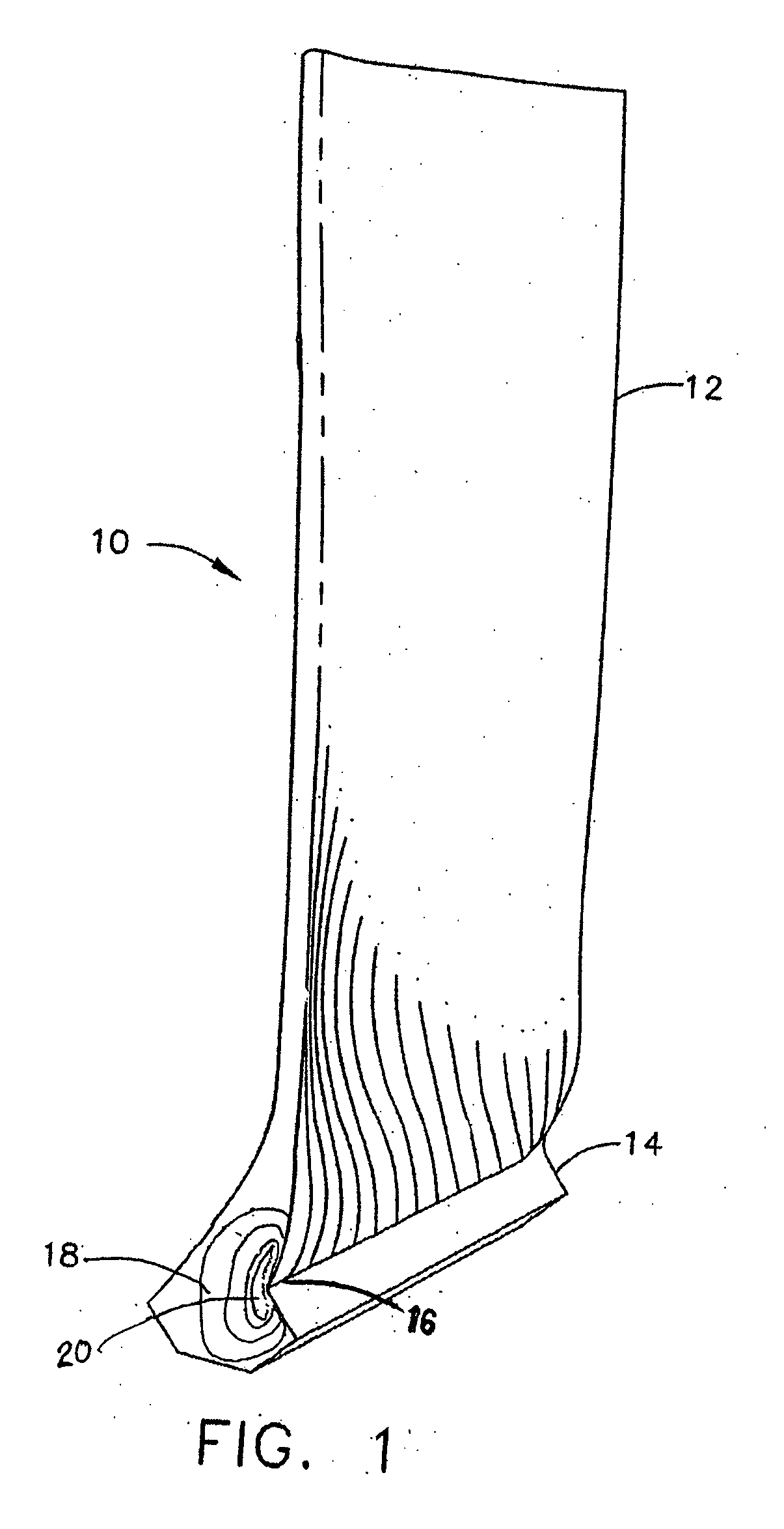
[0020]FIG. 1 depicts an exemplary aircraft engine LPT blade 10. In this illustration a turbine blade 10 comprises a ceramic matrix composite material. The turbine blade 10 includes an airfoil 12 against which the flow of hot exhaust gas is directed. The turbine blade 10 is mounted to a turbine disk (not shown) by a dovetail 14 that extends downwardly from the airfoil 12 and engages a slot (not shown) of similar geometry on a turbine disk. Dovetail 14 includes a fillet radius 16 defined along a line where surfaces of airfoil 12 and dovetail 14 form a concave intersection. FIG. 1 also illustrates ...


PUM

PropertyMeasurementUnit
thickaaaaaaaaaa
thickaaaaaaaaaa
thickaaaaaaaaaa

Abstract

The present invention is a ceramic matrix composite turbine engine component, wherein the component has a region of expected higher interlaminate stress during normal engine operation. The component includes both coated fiber tows and uncoated fiber tows arranged together into a preselected form, wherein the uncoated fiber tows are located at predetermined regions of expected high interlaminate stress. The invention further includes method of manufacturing a CMC such as a composite turbine engine component, wherein the component has a region of expected higher interlaminate stress during engine operation.

Description

[0001] This invention was made with government support under Contract No. N00421-00-3-0536. The government may have certain rights to the invention.FIELD OF THE INVENTION [0002] The present invention relates generally to ceramic matrix turbine engine components, and more particularly, to a heterogeneous material system with intermittent regions of coated and uncoated fibers in a ceramic matrix composite. BACKGROUND OF THE INVENTION [0003] In order to increase the efficiency and the performance of gas turbine engines so as to provide increased thrust-to-weight ratios, lower emissions and improved specific fuel consumption, engine turbines are tasked to operate at higher temperatures. As the higher temperatures reach and surpass the limits of the material comprising the components in the hot section of the engine and in particular the turbine section of the engine, new materials must be developed. [0004] As the engine operating temperatures have increased, new methods of cooling the h...

Claims


Application Information

Patent Timeline
Patent Type & Authority Applications(United States)
IPC IPC(8): B32B9/00
CPCC04B35/565Y10T428/30C04B35/62868C04B35/62871C04B35/62873C04B35/62884C04B35/62894C04B35/62897C04B35/806C04B2235/421C04B2235/524C04B2235/5244F01D5/282F01D5/284Y02T50/67Y02T50/672F05D2300/702F05D2300/2261F05D2300/614C04B35/573C04B35/80Y02T50/60Y10T428/249928Y10T428/249929Y10T428/249931Y10T442/2975
Inventor SUBRAMANIAN, SURESHSTEIBEL, JAMES DALECARPER, DOUGLAS MELTON
Owner GENERAL ELECTRIC CO
Learn More