Storage system and method of storage system path control
a storage system and path control technology, applied in the field of storage system and a method of storage system path control, can solve the problems of ineffective use waste of old type of storage device, and achieve the effect of improving ease of use and reliability, and effective use of storage resources
- Summary
- Abstract
- Description
- Claims
- Application Information
AI Technical Summary
Benefits of technology
Problems solved by technology
Method used
Image
Examples
first embodiment
1. First Embodiment
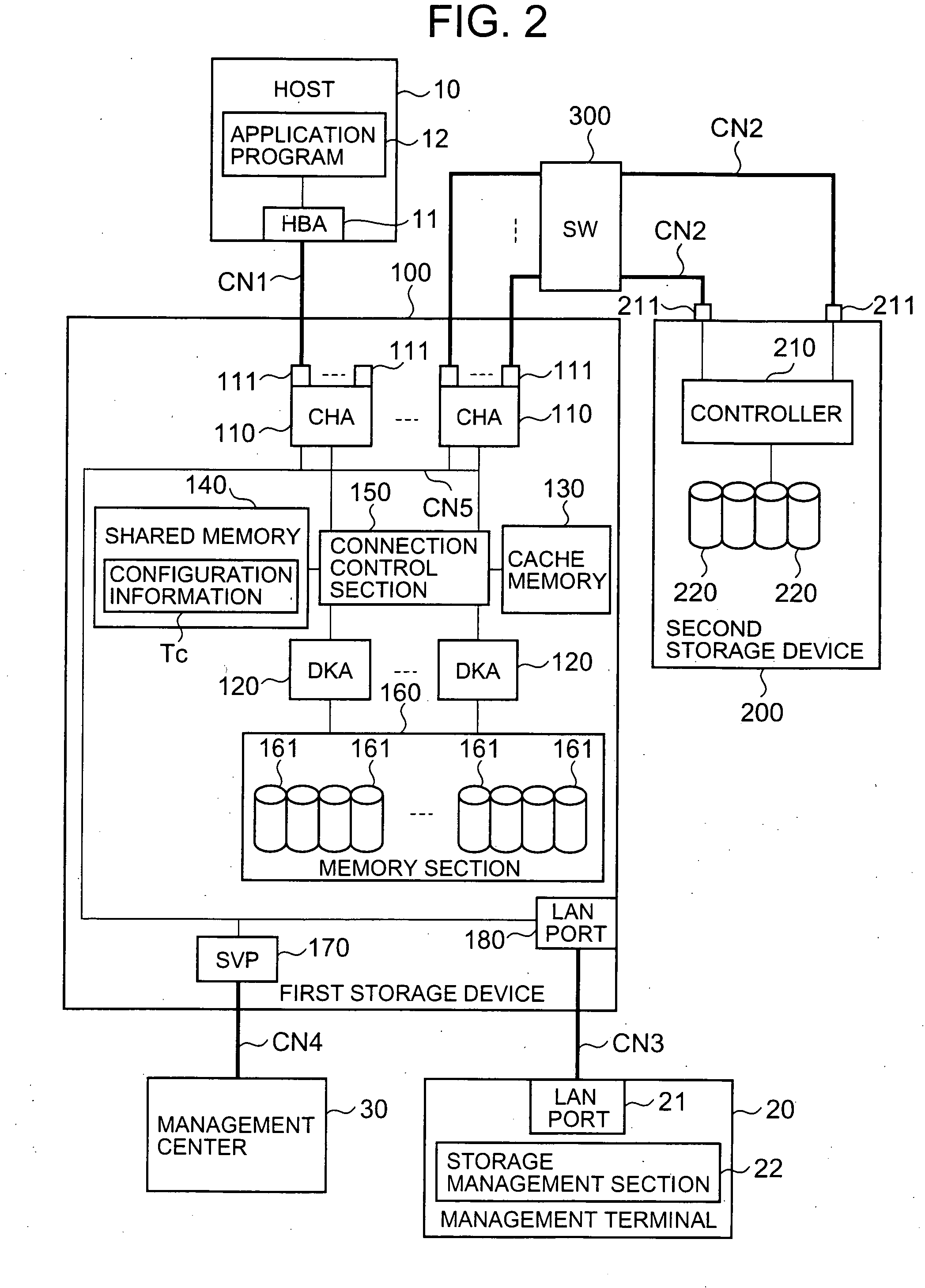
[0077]FIG. 2 is a block diagram showing the configuration of the primary components of the storage system. As described below, this storage system can be, for example, configured to include a host 10, a management terminal 20, a management center 30, a plurality of storage devices 100 and 200, and a switch 300 connecting storage devices 100 and 200.
[0078] The host 10 and first storage device 100 are connected via the communications network CN1. The first storage device 100 and the second storage device 200 are connected via a plurality of communications networks CN2.
[0079] The first storage device 100 and the management terminal 20 are connected via the communications network CN3. Furthermore, the first storage device 100 and the management center 30 are connected via the communications network CN4.
[0080] The host 10 is a computer device comprising information processing resources such as a CPU (Central Processing Unit) and a memory and the like, and is configu...
second embodiment
2. Second Embodiment
[0183] The second embodiment is described based on FIG. 13 through FIG. 15. The following embodiments, including the present embodiment, are equivalent to variations of the first embodiment. In the present embodiment, the first storage device 100 and the second storage device 200 are connected by a plurality of paths, and access requests from the host 10 are processed while these paths are selected in sequence.
[0184]FIG. 13 shows an example of the WWN information management table T3. The WWN information management table T3 is information for the management of the alternate path mode (use mode) of the second storage device 200 being external storage.
[0185] The alternate path mode, can be, for example, the single path mode, or the multi-path mode. The single path mode is a mode wherein one of a plurality of paths is selected for use as described in the first embodiment. The multi-path mode is a mode wherein a plurality of paths are selected in sequence for use as...
third embodiment
3. Third Embodiment
[0194] The third embodiment is described based on FIG. 16 through FIG. 19. In this embodiment, path operation is possible in prescribed units.
[0195]FIG. 16 a flowchart showing an outline of path operation processing. This processing can be executed with the storage management section 22 of the management terminal 20. Firstly, the user calls up the path configuration processing screen (S110), and selects from the menu (S111).
[0196] The operation menu can be, for example, a menu for manipulating path configuration in units of external ports, a menu for manipulating path configuration in units of external storage ports, or a menu for manipulating path configuration in units of external volumes 240.
[0197] When the user desires to process in units of external ports, the user selects the external port to be manipulated (S112). The management terminal 20 displays the configuration of all paths connected to the external port in a list format (S113). The user selects al...
PUM
 Abstract
Description
Claims
Application Information
 - R&D
- Intellectual Property
- Life Sciences
- Materials
- Tech Scout
- Unparalleled Data Quality
- Higher Quality Content
- 60% Fewer Hallucinations
Browse by: Latest US Patents, China's latest patents, Technical Efficacy Thesaurus, Application Domain, Technology Topic, Popular Technical Reports.
© 2025 PatSnap. All rights reserved.Legal|Privacy policy|Modern Slavery Act Transparency Statement|Sitemap|About US| Contact US: help@patsnap.com


