Reference leak

a leakage reference and leakage rate technology, applied in the field of reference leakage, can solve the problems of increased margin of error, inability to artificially control, and sensitive leakage rate of reference leakage to temperatur

a leakage reference and leakage rate technology, applied in the field of reference leakage, can solve the problems of increased margin of error, inability to artificially control, and sensitive leakage rate of reference leakage to temperatur

US20060144120A1Active Publication Date: 2006-07-06TSINGHUA UNIV +1

Image

  • Reference leak
  • Reference leak
  • Reference leak

Examples


Embodiment Construction

[0032] Reference will now be made to the drawings to describe a preferred embodiment of the present invention in detail.

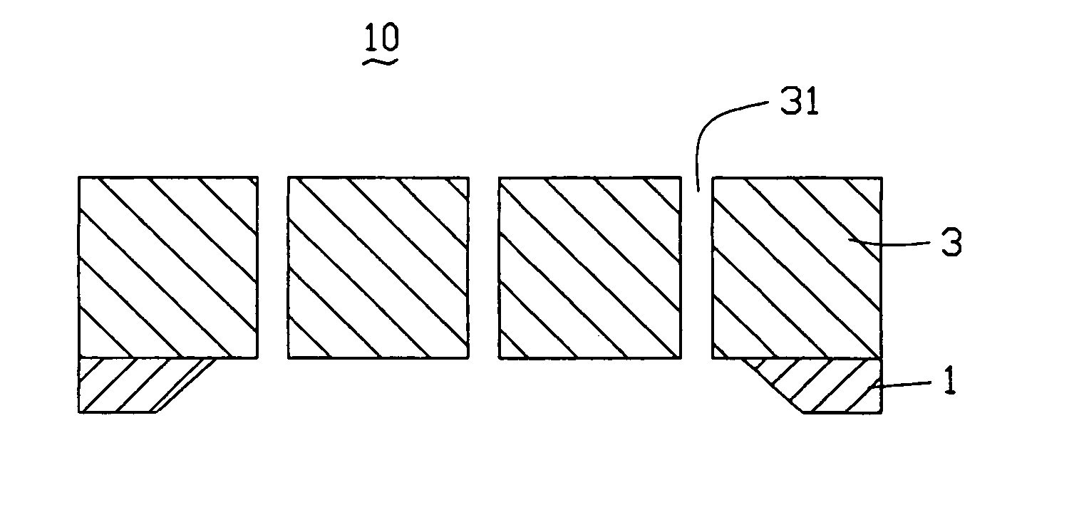
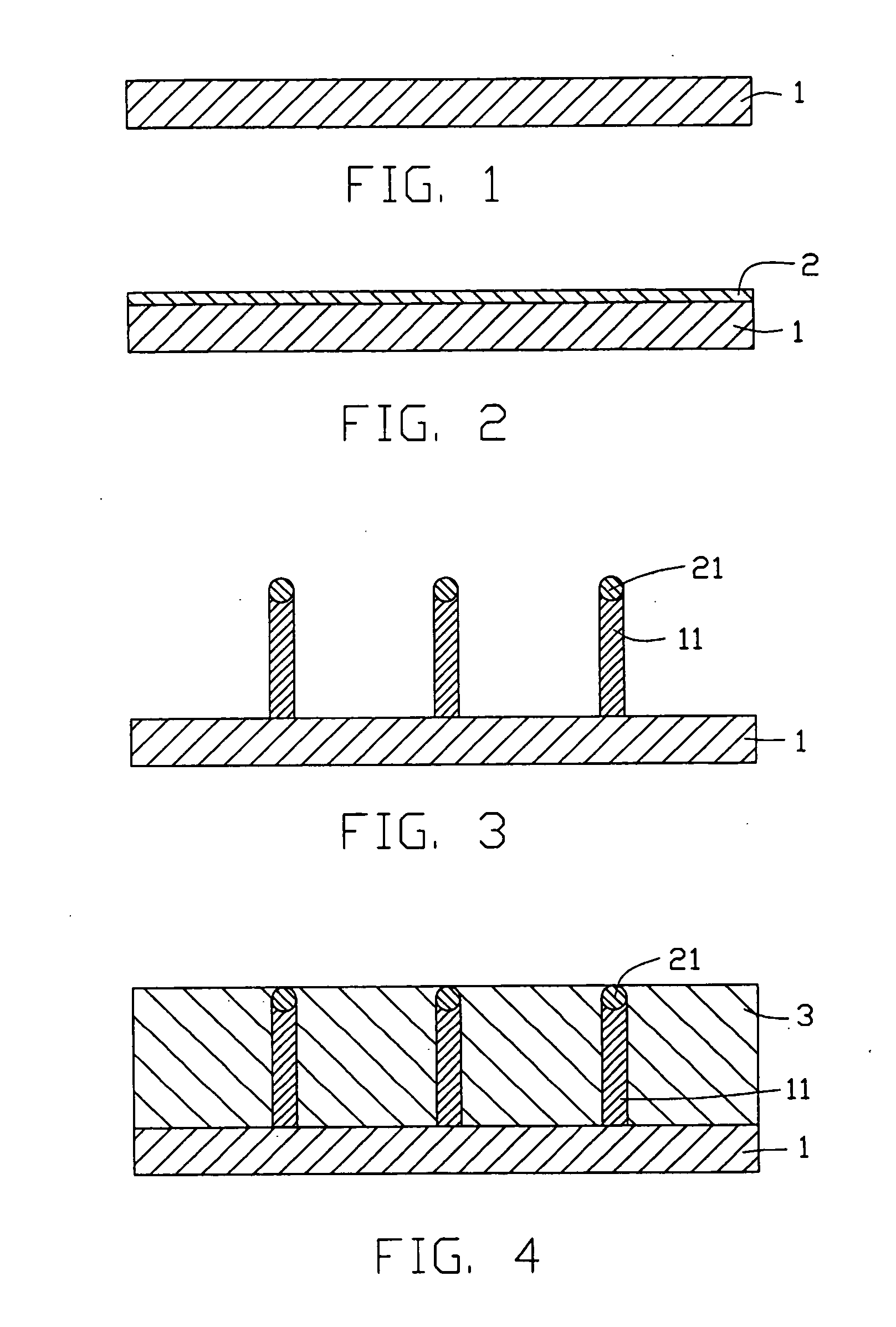
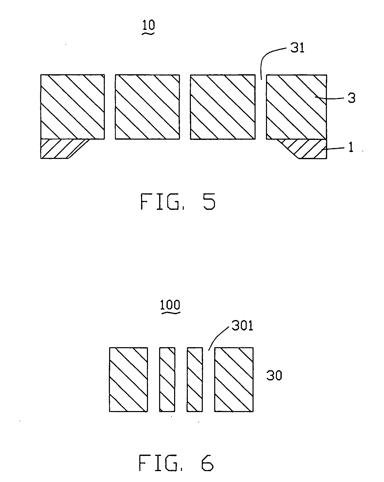
[0033] Referring initially to FIG. 6, a reference leak 100 made by a process according to the preferred embodiment of the present invention is shown. The reference leak 100 comprises a leak layer 30, and a plurality of leak through holes 301 defined in the leak layer 30.

[0034] The leak layer 30 is, advantageously, generally formed of one of a metallic material, a glass material, a composite material, and a ceramic material. The metallic material, if chosen, may usefully be selected from the group consisting of copper, nickel, and molybdenum, and alloys composed substantially of at least one of such metals. The material of the leak layer 30 is selected depending on the specific kind of a gas which the reference leak is utilized to detect. For instance, if the reference leak 100 is utilized to detect He gas, the material of the leak layer 30 is preferably a metalli...


PUM

PropertyMeasurementUnit
diameteraaaaaaaaaa
lengthaaaaaaaaaa
diameteraaaaaaaaaa

Abstract

A reference leak includes a leak layer formed of one of a metallic material, a glass material, and a ceramic material. The metallic material is selected from the group consisting of copper, nickel, and molybdenum. The leak layer comprises a number of substantially parallel leak through holes defined therein. The leak through holes may be cylindrical holes or polyhedrical holes. A length of each of the leak through holes is preferably not less than 20 times a diameter thereof. A diameter of each of the leak through holes is generally in the range from 10 nm to 500 nm. A length of each of the leak through holes is generally in the range from 100 nm to 100 μm. A leak rate of the reference leak is in the range from 10−8 to 10−15 tor×l / s. The leak through holes have substantially same length and diameter.

Description

BACKGROUND OF THE INVENTION [0001] 1. Field of the Invention [0002] The present invention relates to detecting instruments for use in leak detection of a gas, particularly to a reference leak. [0003] 2. Discussion of the Related Art [0004] A reference leak is an artificial instrument for use in leak detection of a specific gas. The reference leak has a constant leak rate for the specific gas under a given condition such as a specific temperature and a specific pressure at the gas intake side. The reference leak has been widely used in periodical leak detection and calibration of a helium mass spectrometer leak detector. [0005] Conventional reference leaks can generally be classified into the three types: platinum wire-glass leaks, squeezed metal tube leaks, and silica membrane helium leaks. A leak rate of the platinum wire-glass leak is generally in the range from 10−6˜10−8 torr·l / s. The platinum wire-glass leak is obtained by implanting a platinum wire into a glass body by way of a...

Claims


Application Information

Patent Timeline
06 Jul 2006
Publication
US20060144120A1
IPC
G01F25/00
CPC
G01M3/007
Inventors
TANG, JIE; LIU, LIANG