FCC feed injection system
a feed and petroleum technology, applied in the direction of lighting and heating apparatus, furniture, transportation and packaging, etc., can solve the problems of inability to instantaneously disperse feed across the catalyst stream, general undesirable effect of fcc unit, and inability to generate light gases
- Summary
- Abstract
- Description
- Claims
- Application Information
AI Technical Summary
Problems solved by technology
Method used
Image
Examples
example 1
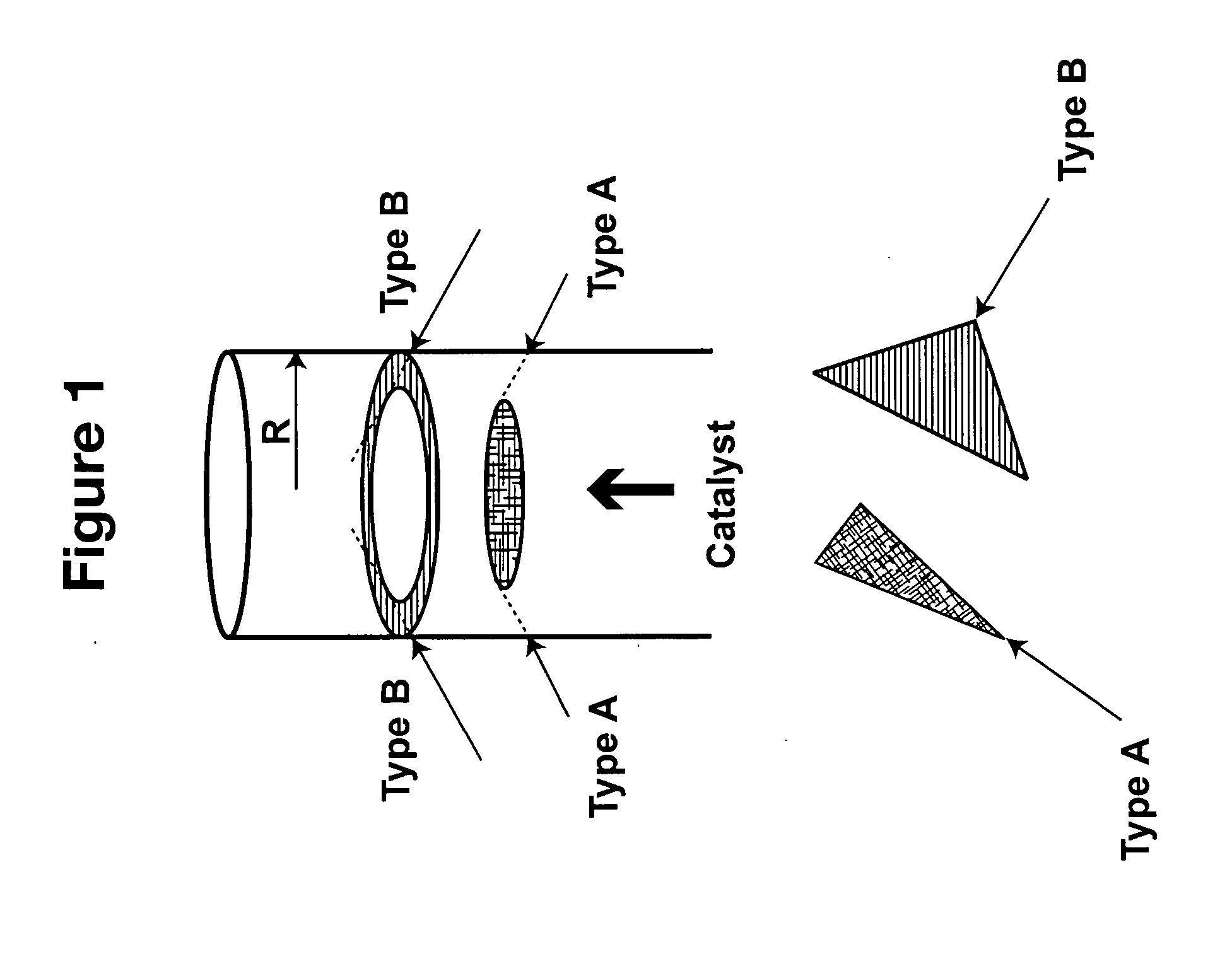
[0051] The shape of the spray patterns for the combination of nozzles is determined by the penetration of each individual spray pattern into the upflowing catalyst stream within the riser. This is illustrated in FIG. 1 which is a schematic diagram showing the penetration of different sprays into the catalyst stream. In FIG. 1, R is the radius of the mixing zone of a stream of catalyst particles as measured from the center of the stream (generally the center of the riser reactor) to the outer edge (generally the wall of the riser reactor). Two different types of nozzles, Type A and Type B, are positioned in a plane symmetrically about the circumference of the riser reactor. The nozzles may be positioned such that the axes of the injected sprays are either coincident with the plane orthogonal to the axis of the flowing catalyst particles or inclined at an angle less than 90° above this plane, and the inclination angles may be different for each type of nozzle.
[0052] The spray pattern...
example 2
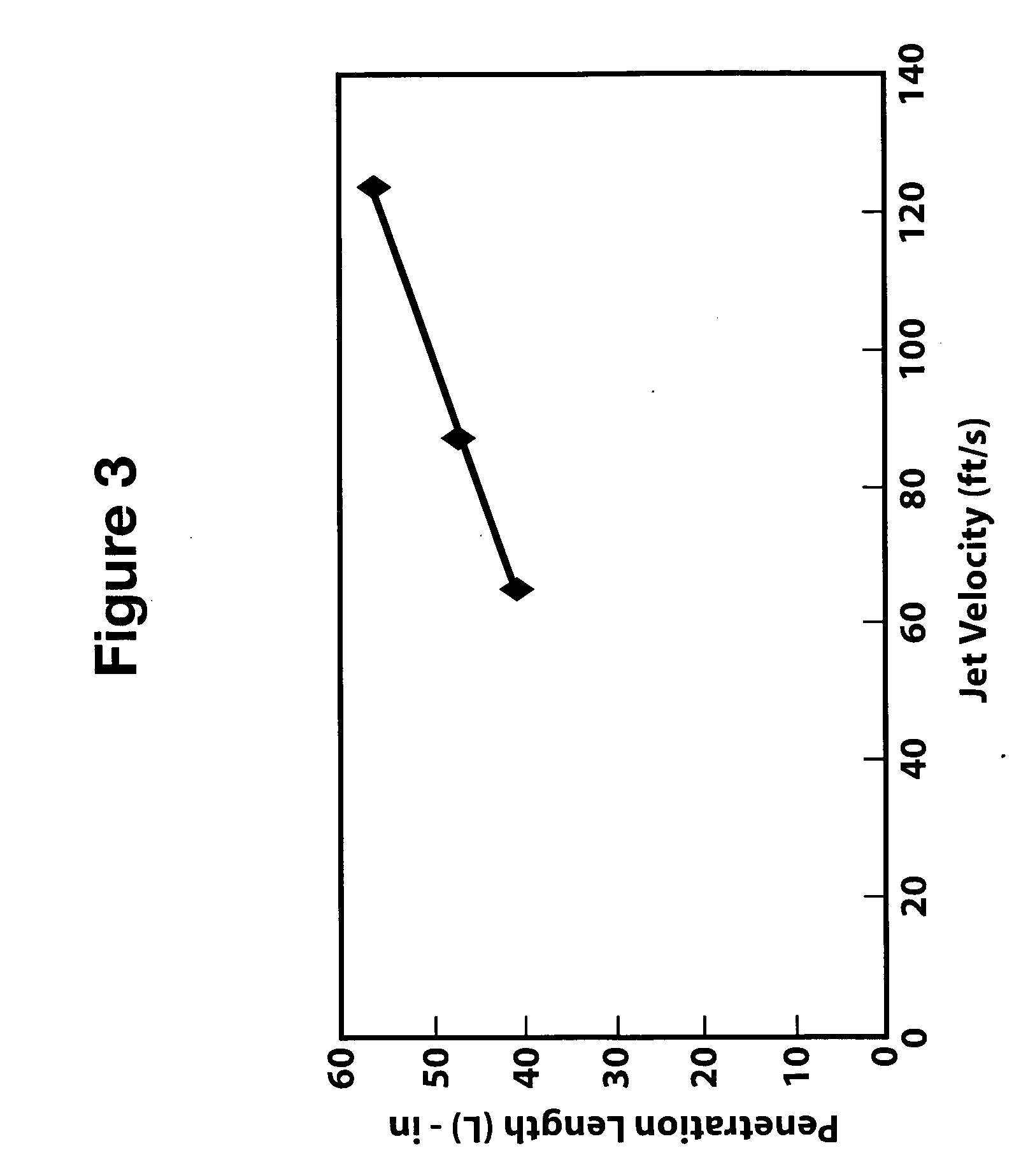
[0060] This example demonstrates the effect of jet velocity on the jet penetration length of the feed. FIG. 3 is a graph showing jet penetration length in inches as a function ofjet velocity of droplets in ft / sec. In FIG. 3, it can be seen that increasing the jet velocity increases the jet penetration length of the spray pattern into the catalyst stream, all other factors being constant.
example 3
[0061] This example demonstrates the effect of feed temperature on the jet penetration length of the feed. FIG. 4 is a graph showing the effect of temperature of the feed on jet penetration length. As shown in FIG. 4, increasing the feed temperature at constant gas / solids temperature will decrease the temperature difference between the gas / solid and oil droplet temperature. This leads to a lower evaporation rate that in turn leads to longer penetration length.
PUM
 Abstract
Description
Claims
Application Information
 - R&D
- Intellectual Property
- Life Sciences
- Materials
- Tech Scout
- Unparalleled Data Quality
- Higher Quality Content
- 60% Fewer Hallucinations
Browse by: Latest US Patents, China's latest patents, Technical Efficacy Thesaurus, Application Domain, Technology Topic, Popular Technical Reports.
© 2025 PatSnap. All rights reserved.Legal|Privacy policy|Modern Slavery Act Transparency Statement|Sitemap|About US| Contact US: help@patsnap.com


