Chemical liquid valve

a liquid valve and liquid technology, applied in the direction of valve operating means/release devices, diaphragm valves, engine diaphragms, etc., can solve the problems of deteriorating parts, high-pressure fluid leakage through a deteriorated portion, and the sealing strength of the valve is reduced with time, so as to achieve stable sealing strength and stable sealing strength. , the effect of stable sealing strength

Inactive Publication Date: 2006-07-06
CKD
View PDF11 Cites 14 Cited by
  • Summary
  • Abstract
  • Description
  • Claims
  • Application Information

AI Technical Summary

Benefits of technology

[0014] The chemical liquid valve is arranged such that the diaphragm is attached to the driving device by inserting the engagement part from the cutout portion of the driving device into the recess, so that the driving force of the driving device is transmitted to the diaphragm. When the valve element is brought out of contact with the valve seat by the driving device, fluid is allowed to flow from the inlet port to the outlet port. When the valve element is brought into contact with the valve seat by the driving device, the flow passage is blocked off to stop the flow of fluid from the inlet port to the outlet port. For example, when the valve element is brought into contact with the valve seat by the driving device if the valve seat contains a little inclination caused by deformation, the valve element is swung (or tilted) along the inclination of the valve seat and accordingly is pressed against the entire valve seat with uniform pressure. Thus, the sealing strength between the valve element and the valve seat is enough to prevent leakage of fluid. Since the valve element is pressed against the valve seat with uniform pressure and therefore the valve seat is unlikely to deteriorate, the sealing strength will hardly change with time. Consequently, the chemical liquid valve of the present invention can prevent leakage of fluid during a valve closed time and provide stable sealing strength. Further, the chemical liquid valve of the present invention can be assembled by simple attachment of the diaphragm to the driving device so that the driving device holds the diaphragm swingably.
[0015] The chemical liquid valve of the present invention is arranged such that the body is made of resin and the valve seat integral with the body is also made of resin. When the valve element is pressed against the valve seat by the driving device, a reaction force is caused in the valve seat against the pressing force of the valve element, pressing up a large-pressing-force portion of the valve element higher than a small-pressing-force portion of the same. Since the valve element swingably held by the driving device can tilt in every direction, it will tilt upon receiving the force from the valve seat. This tilting additionally applies the pressing force to the small-pressing-force portion of the valve element, while reduces the pressing force to the large-pressing-force portion of the valve element. Accordingly, the valve element is pressed against the valve seat with uniform pressure, providing stable sealing strength.
[0016] The chemical liquid valve of the present invention is further arranged such that the driving device is provided with the recess in which the engagement part of the valve element is held with clearance between the engagement part and the recess. Accordingly, the engagement part tilts in the recess to swing the valve element with respect to the driving device. When the valve element is to be brought into contact with the valve seat by the driving device, the valve element tilts along the inclination of the valve seat. When the valve element is to be brought out of contact with the valve seat, on the other hand, the driving device is moved independently until the engagement part engages with the driving device, and then the valve element is lifted to separate from the valve seat. At this time, the valve element is axially lifted up by the driving device. The tilt of the valve element caused when brought into contact with the valve seat will be corrected. According to the chemical liquid valve of the present invention, consequently, the valve element is allowed to swing along the inclination of the valve seat and come into contact with the valve seat with uniform pressure, which can achieve stable sealing strength.

Problems solved by technology

Further, when the valve seat 107 is plastic-deformed, a portion of the valve element 106 to be partially pressed against the valve seat 107 is likely to deteriorate, leading to a decrease in sealing strength with time.
This problem would be especially problematic in the case where the chemical liquid valve 100 is used in the liquid supply line of the semiconductor manufacturing apparatus to control a high-pressure fluid.
Deterioration of the valve seat 107 also may cause leakage of the high-pressure fluid through a deteriorated portion.

Method used


Image

  • Chemical liquid valve
  • Chemical liquid valve
  • Chemical liquid valve

Examples


first embodiment

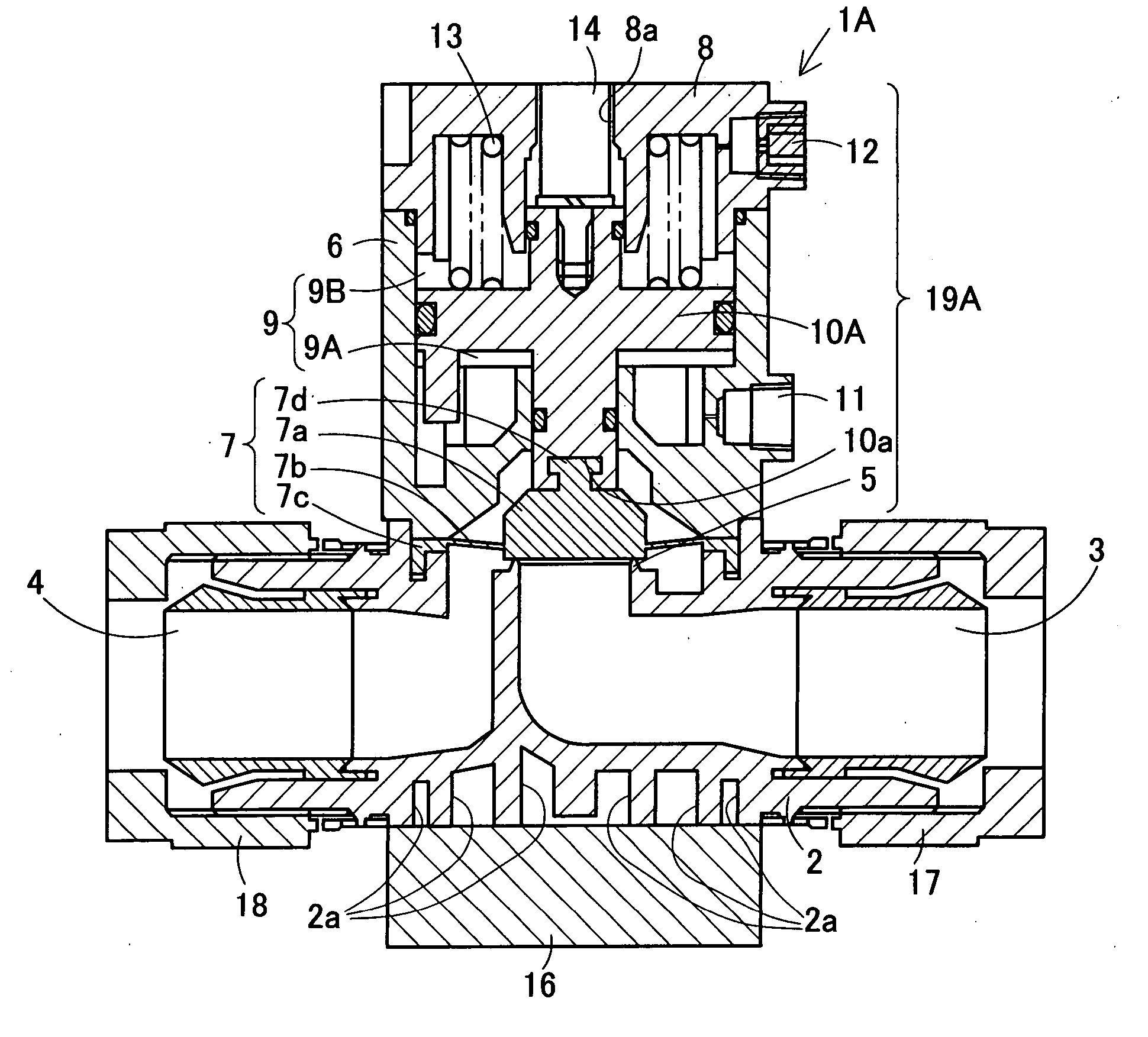
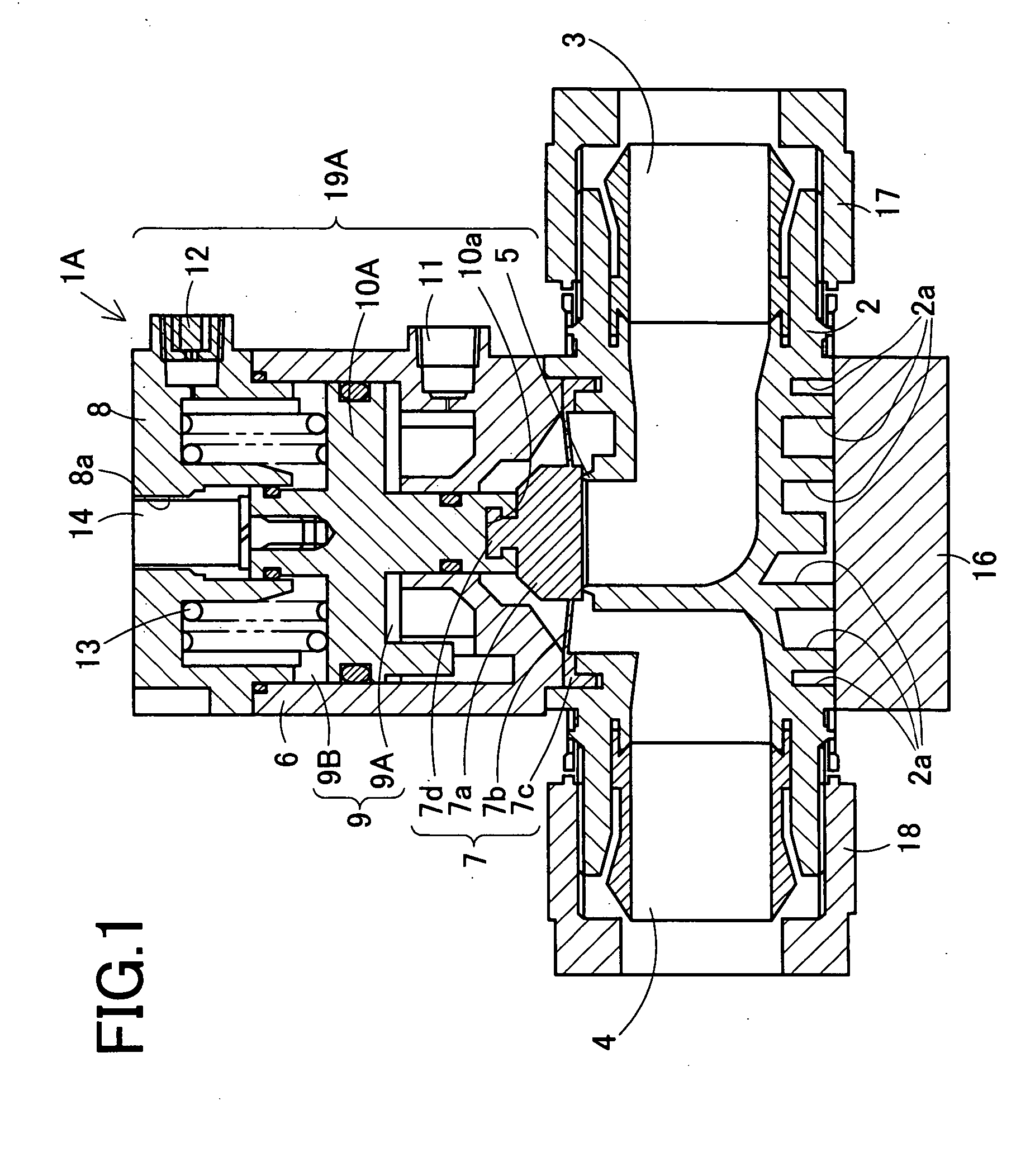
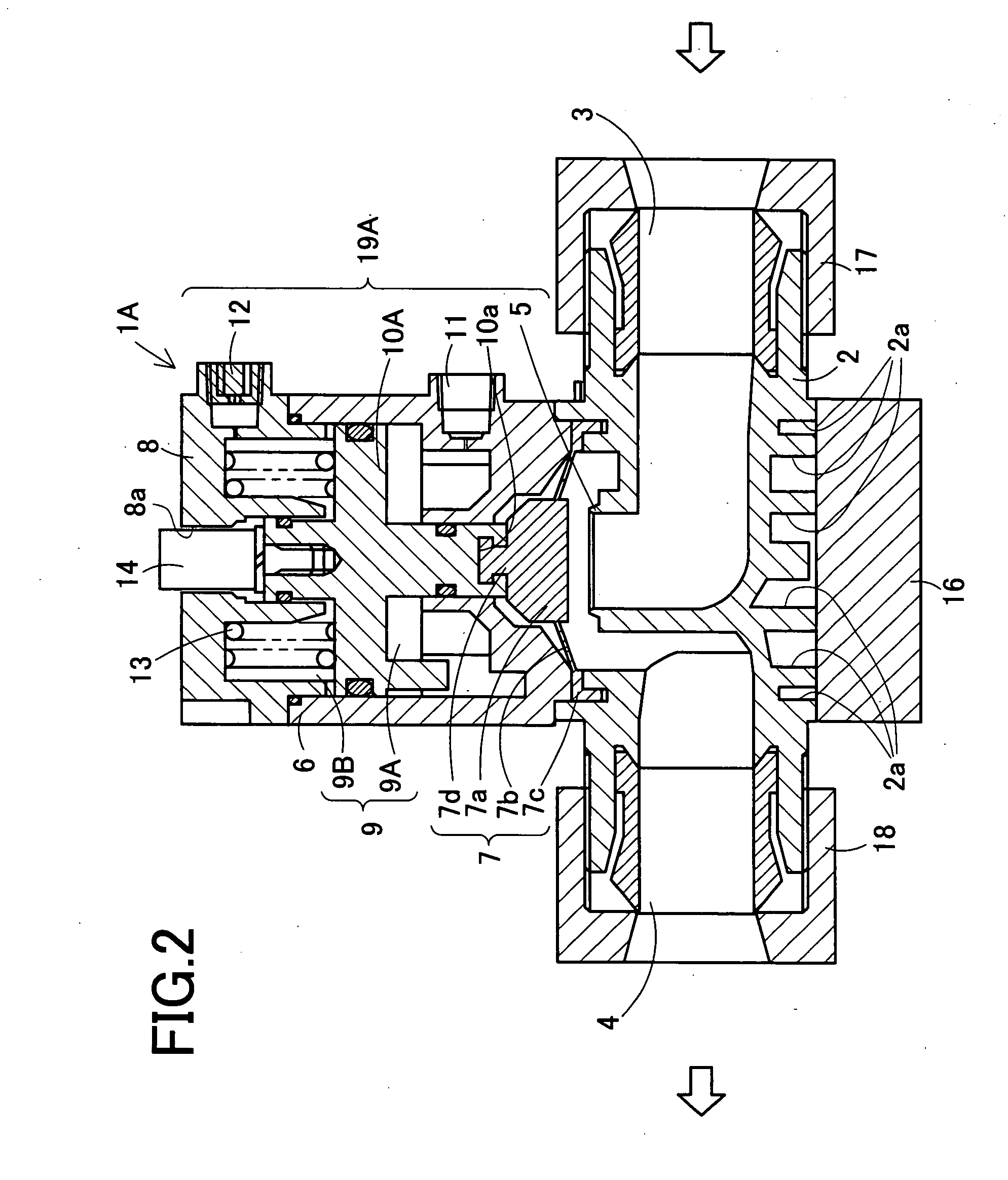
[0029] A chemical liquid valve in a first embodiment of the present invention is first described with reference to accompanying drawings. FIG. 1 is a sectional view of a chemical liquid valve 1A in a valve closed state. FIG. 2 is a sectional view of the chemical liquid valve 1A in a valve open state.

[0030] The chemical liquid valve 1A is located in for example a liquid supply line of a semiconductor manufacturing apparatus and used to control a flow rate of a high-pressure (e.g., about 700 kPa) chemical liquid. The chemical liquid valve 1A includes a body 2 and an actuator assembly 19A coupled to the body 2. The chemical liquid valve 1A is an air-operated valve arranged to bring a diaphragm 7 into / out of contact with a valve seat 5 in association with movements of a piston rod 10A provided in the actuator assembly 19A.

[0031] The body 2 is made of fluorocarbon resin such as PTFE (polytetrafluoroethylene) and PFA (a copolymer of tetrafluoroethylene and a perfluoro(alkyl vinyl ether)...

second embodiment

[0051] Next, a chemical liquid valve in a second embodiment of the present invention will be explained with reference to drawings. FIG. 7 is a sectional view of a chemical liquid valve 1B.

[0052] The chemical liquid valve 1B is substantially identical in basic structure to the chemical liquid valve 1A in the first embodiment but a rubber member 30. Here, the following explanation is made with a focus on such different structure from the chemical liquid valve 1A in the first embodiment. Similar or identical parts are assigned the same referential signs with those in the chemical liquid valve 1A in the first embodiment and therefore the explanations thereof are not repeated here.

[0053] The chemical liquid valve 1B includes a body 2 and an actuator assembly 19B coupled to the body 2. The chemical liquid valve 1B is arranged to bring a diaphragm 7 into / out of contact with a valve seat 5 by sliding a piston rod 10B in a piston chamber 9 to thereby control a flow rate of a chemical liqui...

third embodiment

[0060] Next, a chemical liquid valve of the present invention in a third embodiment is explained with reference to drawings. FIG. 10 is an enlarged view of a valve section of a chemical liquid valve 1C in a valve closed state.

[0061] The chemical liquid valve 1C is substantially identical in basic structure to the chemical liquid valve 1A in the first embodiment excepting that a diaphragm 40 and an engagement member 41 are made as separate members. Here, the following explanation is made with a focus on such different structure from the chemical liquid valve 1A in the first embodiment. Similar or identical parts are assigned the same referential signs with those in the chemical liquid valve 1A in the first embodiment and therefore the explanations thereof are not repeated here.

[0062] The chemical liquid valve 1C includes a body 2 and an actuator assembly 19A coupled to the body 2 with a connecting member not shown. The chemical liquid valve 1C is arranged to bring the diaphragm 40 ...


PUM


Abstract

A chemical liquid valve is arranged such that a diaphragm coupled to a piston rod is brought into/out of contact with a valve seat provided between an inlet port and an outlet port. To achieve a chemical liquid valve providing stable sealing strength, the diaphragm includes an engagement part whose top end is formed in semispherical shape, which is inserted and engaged in a recess of the piston rod so that the engagement part of the diaphragm comes into point contact with an inner wall of the recess of the piston rod. Thus, the piston rod swingably holds the diaphragm.

Description

CROSS-REFERENCE TO RELATED APPLICATIONS [0001] This application is a continuation application based upon and claims the benefit of the prior PCT International Patent Application No. PCT / JP2004 / 013739 filed on. Sep. 21, 2004, the entire contents of which are incorporated herein by reference.BACKGROUND OF THE INVENTION [0002] 1. Field of the Invention [0003] The present invention relates to a chemical liquid valve arranged such that a valve element coupled to a driving device is brought into / out of contact with a valve seat placed between an inlet port and an outlet port. [0004] 2. Description of Related Art [0005] In a conventional manufacturing line for semiconductors, medical products, and others, a chemical liquid valve has been used to control a chemical liquid such as purified water, acid, and alkali. FIG. 11 is a sectional view of a chemical liquid valve 100 in a prior art. [0006] The chemical liquid valve 100 has a body 103 formed with an inlet port 101 and an outlet port 102,...

Claims


Application Information

Patent Timeline
Patent Type & Authority Applications(United States)
IPC IPC(8): F16K31/143F16K7/17F16K1/00F16K1/32F16K7/14F16K31/122F16K41/12
CPCF16K7/14F16K31/1221F16K41/12F16K1/36F16K1/42F16K7/17H01L21/02
Inventor MASAMURA, AKINORIOSUGI, SHIGERU
Owner CKD
Why Eureka
Try Eureka