Interdigitating diffractive light modulator

a diffractive light and interdigitation technology, applied in the field of interdigitation-type diffractive light modulators, can solve the problems of increasing manufacturing costs, requiring a large area, and conventional glv devices having reached the limit of miniaturization, and achieve the effect of improving diffraction efficiency

Inactive Publication Date: 2006-07-06
SAMSUNG ELECTRO MECHANICS CO LTD
View PDF1 Cites 7 Cited by
  • Summary
  • Abstract
  • Description
  • Claims
  • Application Information

AI Technical Summary

Benefits of technology

[0022] Accordingly, the present invention has been made keeping in mind the above problems occurring in the prior art, and an object of the present invention is to provide an interdigitation-type diffractive light modulator which is able to enhance diffraction efficiency despite using only one pair of ribbons.
[0023] Another object of the present invention is to provide an interdigitation-type diffraction light modulator which increases the diffraction angle of diffractive light, thus easily distinguishing between a zero order diffraction and a first order diffraction.

Problems solved by technology

However, this increases manufacturing costs and requires a large area.
Thus, conventional GLV devices have reached the limit of miniaturization.

Method used


Image

  • Interdigitating diffractive light modulator
  • Interdigitating diffractive light modulator
  • Interdigitating diffractive light modulator

Examples


first embodiment

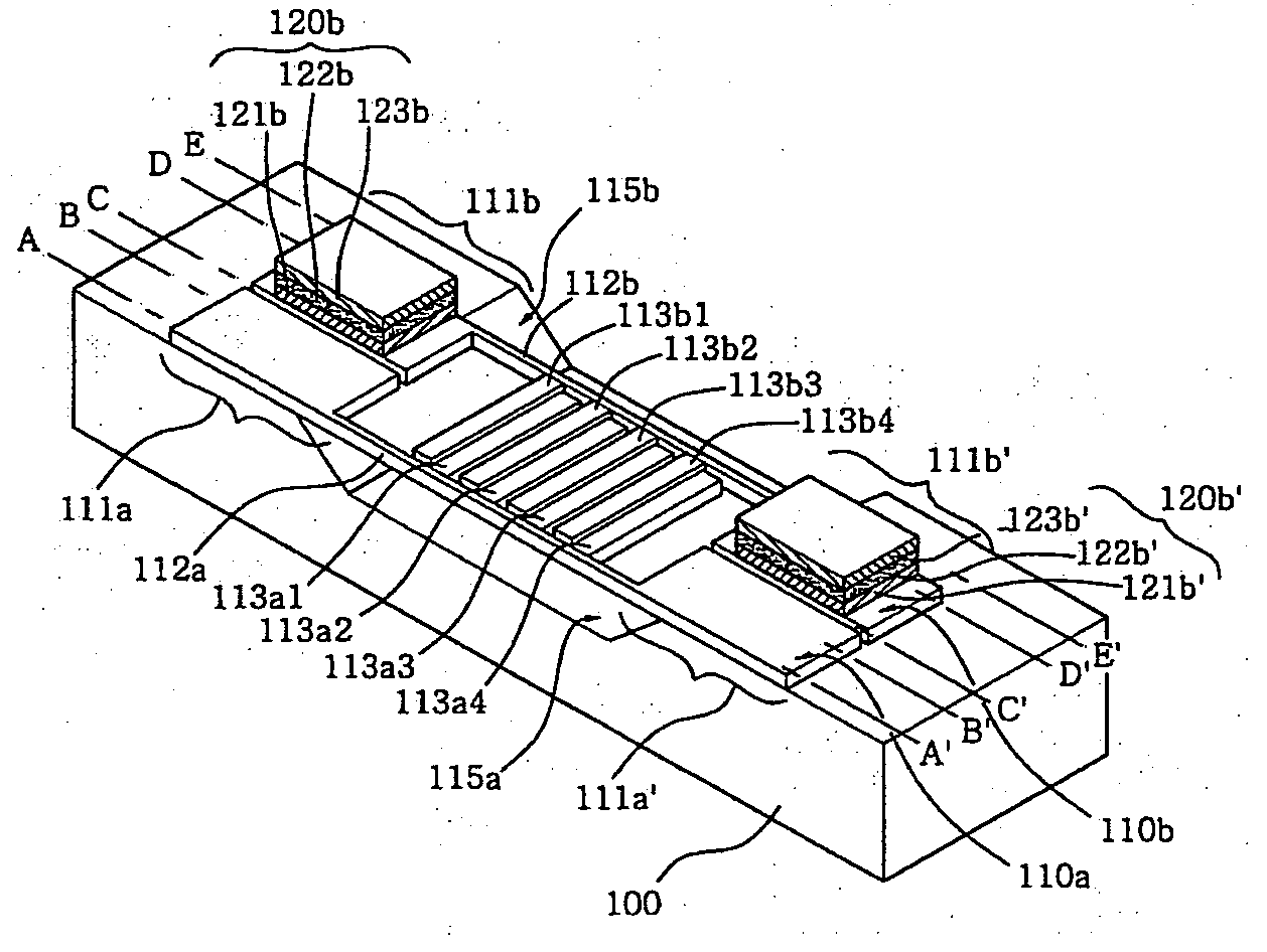
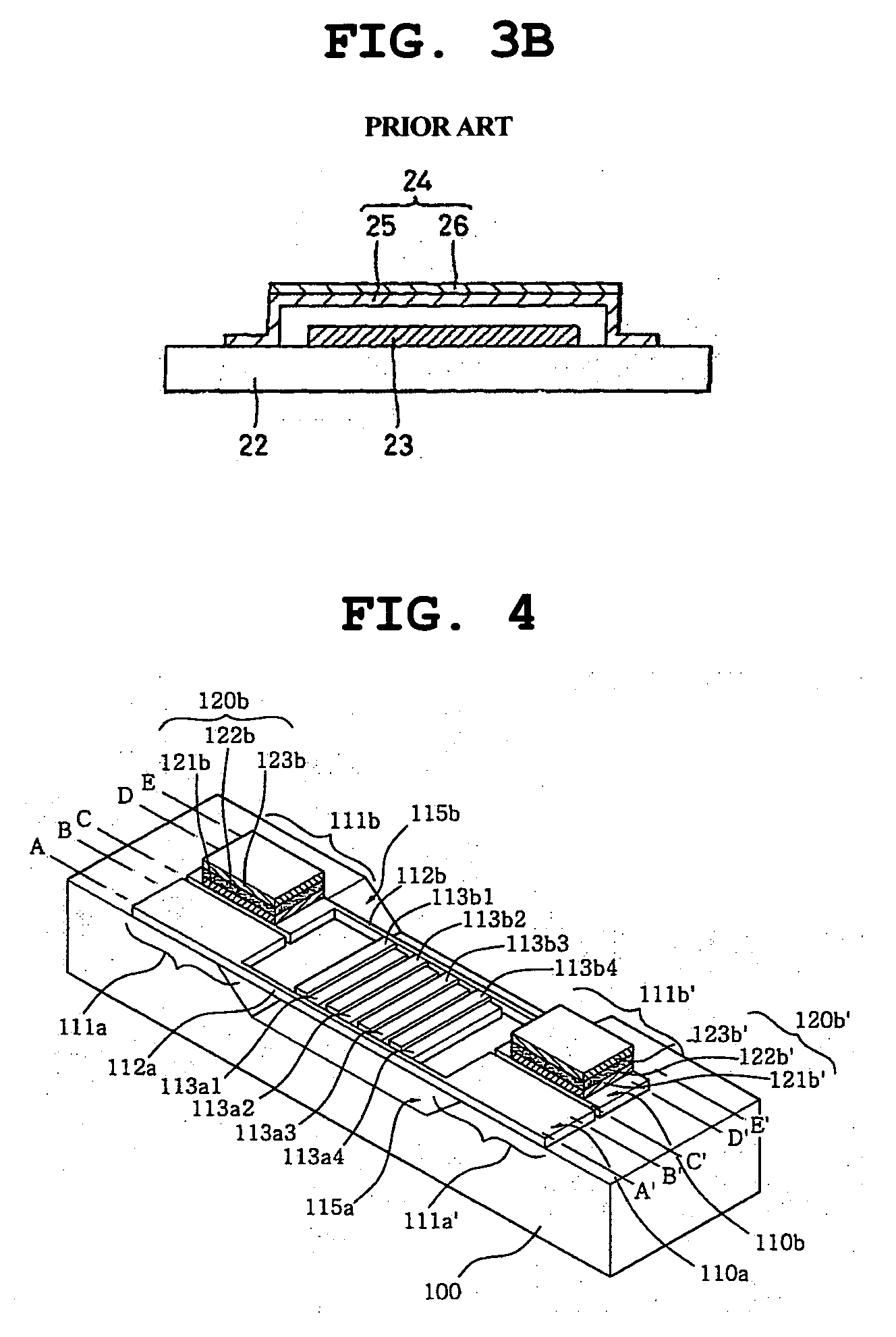
[0038]FIG. 4 is a perspective view of an interdigitation-type diffractive light modulator, according to the present invention.

[0039] Referring to FIG. 4, the interdigitation-type diffractive light modulator according to the first embodiment includes a substrate 100 and a pair of ribbons 110a and 110b.

[0040] The substrate 100 has a recess. Each ribbon 110a, 110b has a pair of support parts 111a and 111a′, 111b and 111b′ which are fastened to both sides of an upper surface of the substrate 100 other than the recess, so that the ribbon 110a, 110b is laid across the recess on the substrate 100 in a bridge shape. Here, the recess of the substrate 100 provides a space to allow an intermediate portion of the ribbon 110a or 110b to move upwards and downwards.

[0041] The substrate 100 is an insulated substrate, such as a glass substrate or a substrate which is made by forming an insulating layer on a semiconductor substrate, such as a silicon (Si) or gallium-arsenide (GaAs) substrate.

[0042...

second embodiment

[0064]FIG. 6 is a perspective view of an interdigitation-type diffractive light modulator, according to the present invention.

[0065] Referring to FIG. 6, the interdigitation-type diffractive light modulator according to the second embodiment includes a substrate 200 having a recess, and a pair of ribbons 210a and 210b each of which includes a diffractive part 215a, 215b having a fishbone shape.

[0066] Each ribbon 210a, 210b has a pair of support parts 211a and 211a′, 211b and 211b′ which are fastened to both sides of an upper surface of the substrate 200 other than the recess so that the ribbon 210a, 210b is laid across the recess on the substrate 200 in a bridge shape. Here, the recess of the substrate 200 provides a space to allow an intermediate portion of the ribbon 210a or 210b to move upwards and downwards.

[0067] As such, each ribbon 210a, 210b has the pair of support parts 211a and 211a′, 211b and 211b′ and the diffractive part 215a, 215b which has a fishbone shape and is pr...


PUM


Abstract

Disclosed herein is an interdigitation-type diffractive light modulator. In the interdigitation-type diffractive light modulator of the present invention, each of a pair of ribbons has a plurality of diffractive branches which are arranged in a comb shape, and the diffractive branches of the ribbons interdigitate with each other. Furthermore, the respective ribbons moves upwards and downwards or, alternatively, one ribbon moves upwards and downwards, so that the diffractive branches of the ribbons which interdigitate with each other form a stepped structure, thus diffracting incident light.

Description

BACKGROUND OF THE INVENTION [0001] 1. Field of the Invention [0002] The present invention relates generally to diffractive light modulators and, more particularly, to an interdigitation-type diffractive light modulator in which each of a pair of ribbons has a plurality of diffractive branches arranged in a comb shape, and in which the diffractive branches of the ribbons interdigitate with each other, and the respective ribbons move upwards and downwards or, alternatively, one ribbon moves upwards and downwards, so that the diffractive branches of the ribbons which interdigitate with each other form a stepped structure, thus diffracting incident light. [0003] 2. Description of the Related Art [0004] Recently, with the development of micro-technology, MEMS (micro-electro-mechanical systems) devices and micro-apparatuses to assemble the MEMS devices are gaining popularity. [0005] The MEMS devices form a microstructure on a substrate, such as a silicon substrate and a glass substrate, i...

Claims


Application Information

Patent Timeline
Patent Type & Authority Applications(United States)
IPC IPC(8): G02B26/00
CPCG02B26/0808B81C1/00142G02B26/0841G02B26/085G02B26/0858Y10S359/904
Inventor AN, SEUNG DOHONG, YOON SHIKHAN, SEUNG HEONYI, HYUN JU
Owner SAMSUNG ELECTRO MECHANICS CO LTD
Why Eureka
Try Eureka