High frequency signal transmission line having reduced noise

Inactive Publication Date: 2006-07-06
SAMSUNG ELECTRO MECHANICS CO LTD
View PDF4 Cites 54 Cited by
  • Summary
  • Abstract
  • Description
  • Claims
  • Application Information

AI Technical Summary

Benefits of technology

[0025] Accordingly, the present invention has been made keeping in mind the above problems occurring in the related art, and an object of the

Problems solved by technology

In general, high frequency signal transmission and high-speed switching of chips of electronic systems cause undesired noise due to electromagnetic interference.
Thus, it is difficult to transmit the signal due to crosstalk noise generated by the two kinds of wires.
Far-end crosstalk noise occurs when the signal is transmitted to the far end of the line.
Although far-end crosstalk noise has a much smaller signal width than near-end crosstalk noise, it has a large magnitude, thus causing incorrect switching operation.
Further, reflection noise is generated upon mismatching of characteristic impedance or terminating resistance between the high frequency signal transmission line and the line adjacent to the transmission line.
Reflection noise generated at the far end of the transmission line affects the near-end crosstalk noise.
Further, radiation noise is generated by a closed loop while the signal is transmitted along the closed loop that is formed in the signal transmission line.
Thus, although the conventional structures are effective for reducing crosstalk noise, they have almost no effect of reducing reflection noise on a substrate having a high wire density.
In

Method used


Image

  • High frequency signal transmission line having reduced noise
  • High frequency signal transmission line having reduced noise
  • High frequency signal transmission line having reduced noise

Examples


Embodiment Construction

[0034] Hereinafter, a detailed description will be given of the present invention, with reference to the appended drawings.

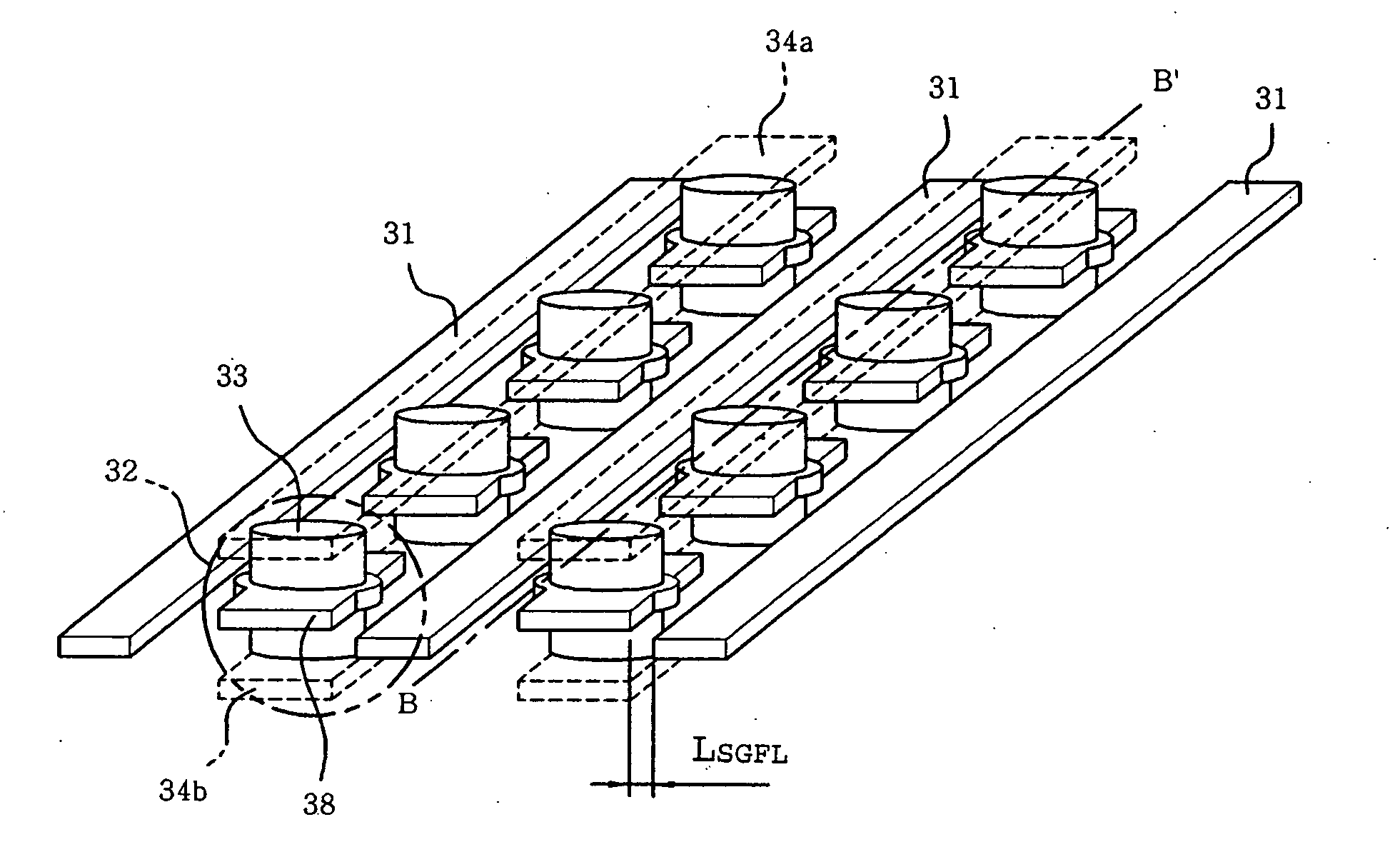
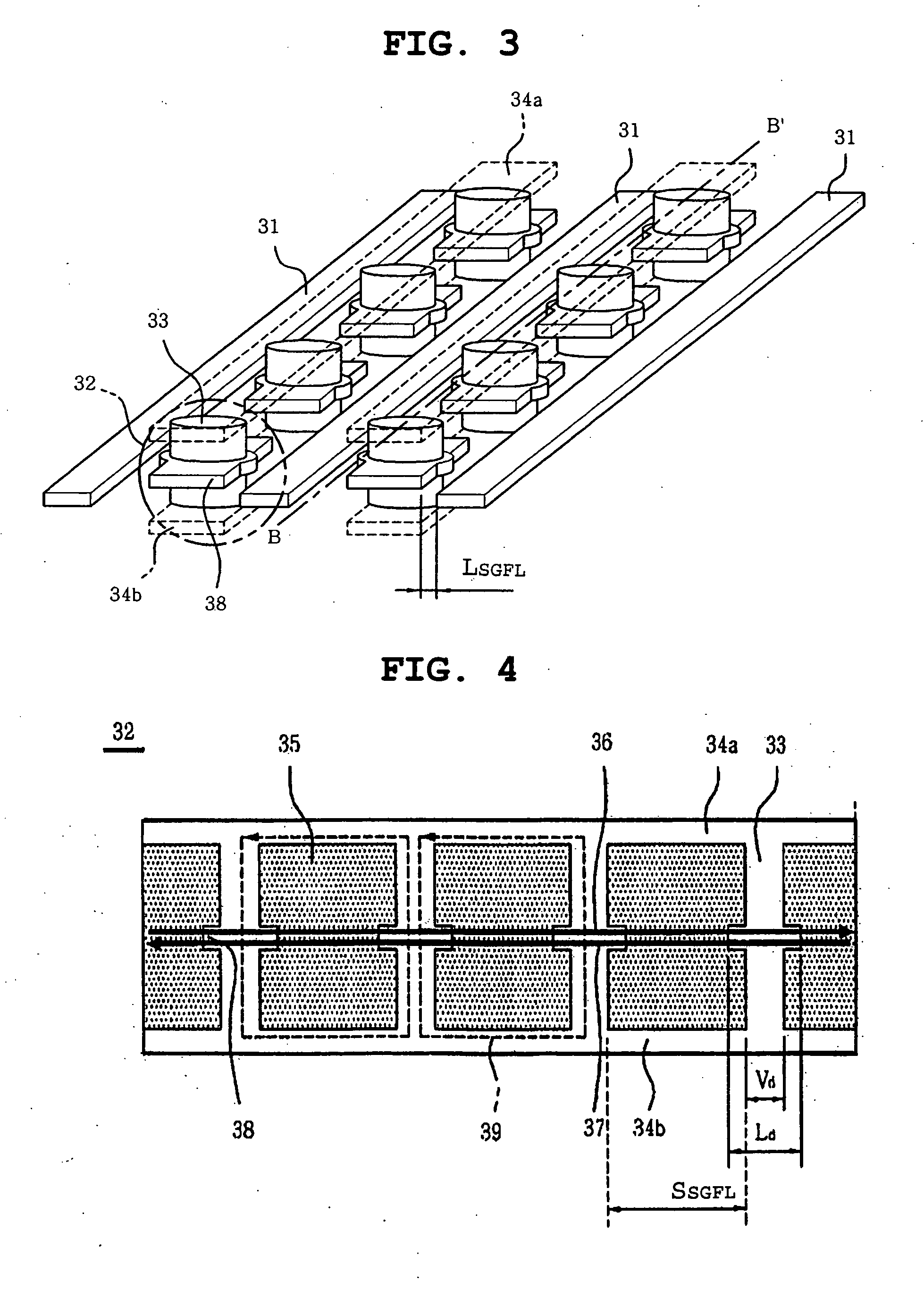
[0035]FIG. 3 is a perspective view showing a PCB for high frequency signal transmission according to the present invention, and FIG. 4 is a sectional view taken along the line B-B′ of FIG. 3, which shows ground line blocks 32, via holes 33 and ground electrodes 34a and 34b.

[0036] As shown in FIG. 3, the PCB for high frequency signal transmission of the present invention is a multilayer PCB, one layer of which includes a plurality of signal transmission lines 31 to transmit a high frequency signal, and a plurality of ground line blocks 32 disposed between the signal transmission lines 31 to shield against noise. The ground line blocks 32 each have a via hole 33 formed therethrough. In addition, the ground line block 32 may include a land part 38 for connection to the via hole 33.

[0037] On the upper and lower surfaces of the ground line blocks 32, the ground el...


PUM


Abstract

A high frequency signal transmission line having reduced noise. Particularly, a signal transmission line of the current invention has reduced radiation noise and reflection noise, because a conventional ground guard fence line disposed between signal lines is separated into a plurality of ground line blocks that are spaced apart from each other to shield against noise.

Description

INCORPORATION BY REFERENCE [0001] The present application claims priority under 35 U.S.C. §119 to Korean Patent Application No. 10-2004-0116802 filed on Dec. 30, 2004. The content of the application is incorporated herein by reference in its entirety. BACKGROUND OF THE INVENTION [0002] 1. Field of the Invention [0003] The present invention relates, generally, to a high frequency signal transmission line having reduced noise. More particularly, the present invention relates to a signal transmission line having reduced radiation noise and reflection noise, by separating a conventional ground guard fence line disposed between signal lines into a plurality of ground line blocks that are spaced apart from each other to shield against noise. [0004] 2. Description of the Related Art [0005] In general, high frequency signal transmission and high-speed switching of chips of electronic systems cause undesired noise due to electromagnetic interference. Particularly, a printed circuit board (PC...

Claims


Application Information

Patent Timeline
IPC IPC(8): H02B1/00
CPCH05K1/0219H05K2201/09618H05K9/00
Inventor KIM, YOUNG WOORYU, CHANG MYUNGKIM, HANCHAE, WOO LIM
Owner SAMSUNG ELECTRO MECHANICS CO LTD
Why Eureka
Try Eureka