
System and method for data communication over power lines

a data communication and power line technology, applied in the field of system and a method for data communication over power lines, can solve the problems of poor stop-band attenuation, corresponding electromagnetic radiation emissions, communication bandwidth must be shared, etc., and achieve the effect of optimizing interference reduction

Inactive Publication Date: 2006-07-06
ACN ADVANCED COMM NETWORK
View PDF17 Cites 54 Cited by
  • Summary
  • Abstract
  • Description
  • Claims
  • Application Information

AI Technical Summary

Benefits of technology

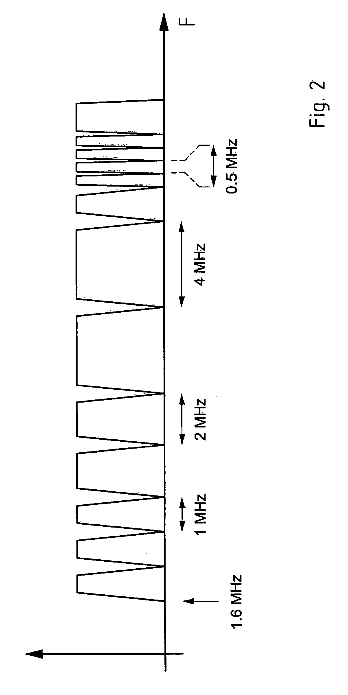
"The present invention provides a system and method for data communication over power lines that allows for high data communication rates, simultaneous and asynchronous data transmissions, and the use of different transmit power levels. The method involves dividing the power line channel bandwidth into n sub-channels, and detecting communication activity in a pre-selected subset of the sub-channels to identify one free sub-channel for transmitting data. The data is modulated and received using symbol synchronization and time-domain equalization. The invention allows for multiple power line modems to communicate in parallel, leading to optimally reduced interferences between the sub-channels and no single point of failure."

Problems solved by technology

Although OFDM techniques allow for higher data rates than time division multiple access techniques, they have a major drawback in that they have poor stop-band attenuation.
Disadvantages of the master-slave approach are that the transmit level of the master station must be high enough to allow to reach the most distant slave modem and that the communication bandwidth must be shared between several slave modems.
Main disadvantages of the prior art systems for data communication over electric power distribution lines are: a high transmit level needed to reach the most distant slave modem, resulting in corresponding electromagnetic radiation emissions, complex random access schemes required to control the permission to transmit of the slave modems, the master station represents a single point of failure, and the need for time synchronization between different master stations to avoid interferences between the ongoing simultaneous power line communications, if several power line master-slave systems are used at the same time.
These drawbacks are main barriers to the broad deployment of power line communication.

Method used


Image

  • System and method for data communication over power lines
  • System and method for data communication over power lines
  • System and method for data communication over power lines

Examples


Embodiment Construction

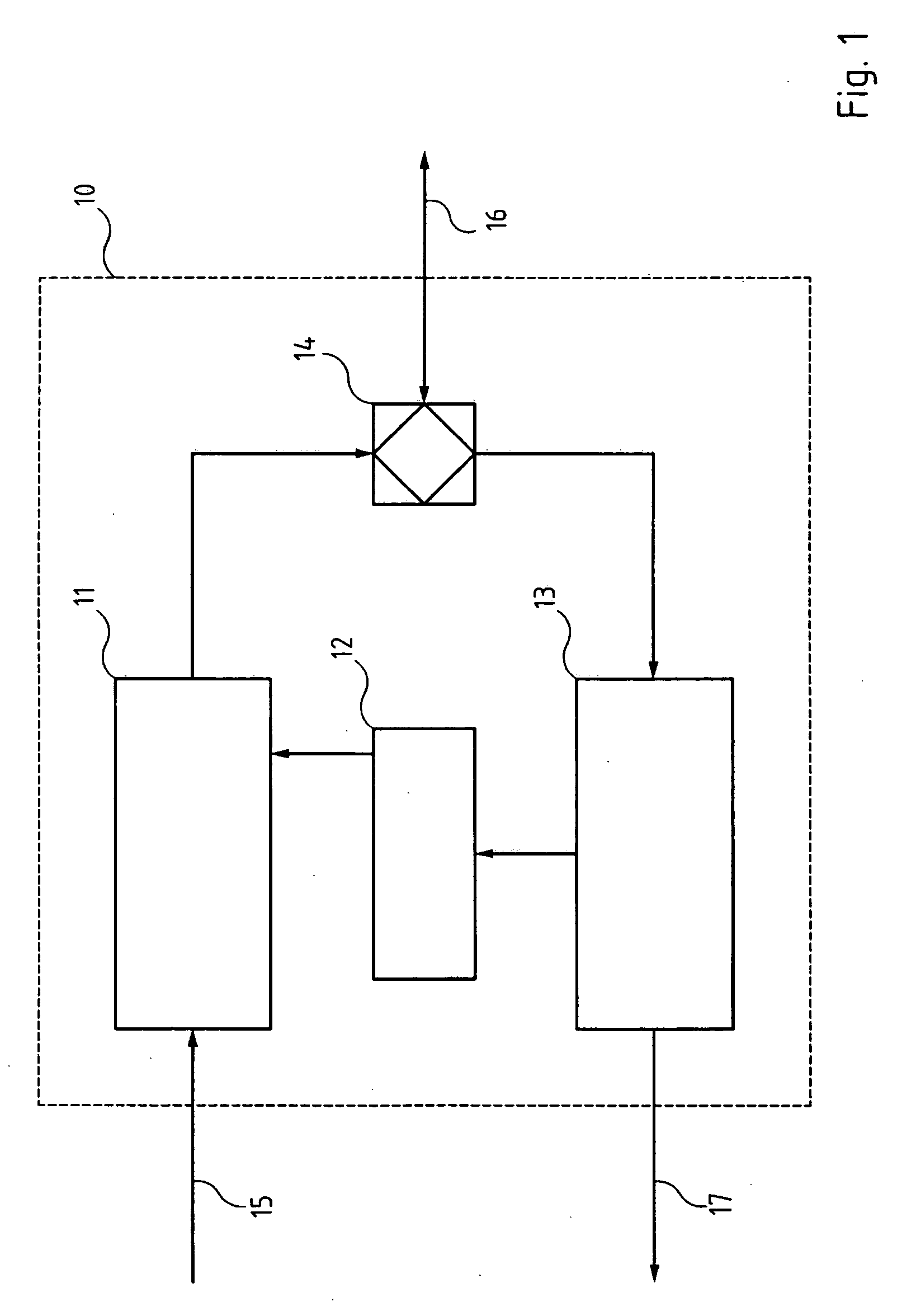
[0031]FIG. 1 is a block diagram of a transceiver system 10 implemented in a power line modem in accordance with a preferred embodiment of the present invention. The transceiver system preferably includes a sender 11 based for example on a discrete cosine modulated filter bank or on a wavelet packet modulated filter bank and a receiver 13 also based for instance on a discrete cosine modulated filter bank or on a wavelet packet modulated filter bank. A data communication activity detector 12 is connected to the receiver 13. The sender 11 and the receiver 13 are connected to the hybrid circuit 14 over which the transceiver system 10 is connected to the electric power distribution network 16.

[0032] According to a preferred embodiment of the invention, the transceiver system implemented in the inventive power line modem comprises a sender 11 and a receiver 13. It is therefore able to both transmit and receive data, possibly at the same time and on different sub-channels. The one skilled...


PUM


Abstract

A system and a method are proposed for broadband communications over power lines comprising the area of the low-voltage transformer to the house connection unit and / or the electricity distribution inside the house. The new method allows for several parallel asynchronous data communications in different sub-channels with individual transmit power in each sub-channel. Sub-channel separation uses pass-band filters with high stop-band attenuation. High data rate in each sub-channel is achieved through the use of discrete wavelet multi-tone modulation. Coarse synchronization in each sub-channel and the optimization of the coefficients of the time-domain equalizer are carried out using a training sequence.

Description

REFERENCE DATA [0001] This application is a continuation of international PCT application 2004WO-EP05048 (WO04091113) filed on Apr. 7, 2004 under priority of European application EP03100939.2 of Apr. 8, 2003, the contents of which are hereby incorporated by reference.FIELD OF THE INVENTION [0002] The invention relates to a system and a method for broadband data communications over a power line distribution network comprising the area between the low-voltage transformer station and the house connection unit and / or the electricity distribution within the house. BACKGROUND ART AND ASSESSMENT THEREOF [0003] Prior art systems for data communication over electric power distribution lines, for example between a low-voltage transformer station and a house connection unit and / or within a house, commonly use at least one master station and slave modems which have to register to the master station. The same network architecture is also used for broadband data communications over the electricit...

Claims


Application Information

Patent Timeline
Patent Type & Authority Applications(United States)
IPC IPC(8): H04J15/00H04B3/54H04L5/16H04L5/22G05B11/01G08B1/08H04J99/00H04L5/06
CPCH04B3/54H04B2203/5416H04L5/06
Inventor HORVATH, STEPHANJAMIN, ANTONY
Owner ACN ADVANCED COMM NETWORK
Learn More