[0004] In certain embodiments, a device is provided for the detection of a structure to be applied to a substrate and suitable pertinent methods such that, on the one hand, direct inspection of the structure applied is feasible and, on the other hand, inspection is easy to perform.
[0005] Moreover, a device and method are provided for the detection of a structure to be applied to a substrate, including for subsequent inspection, such that, on the one hand, subsequent inspection is feasible in a simple fashion, and, on the other hand, an accurate
error analysis for the structure to be applied is provided.
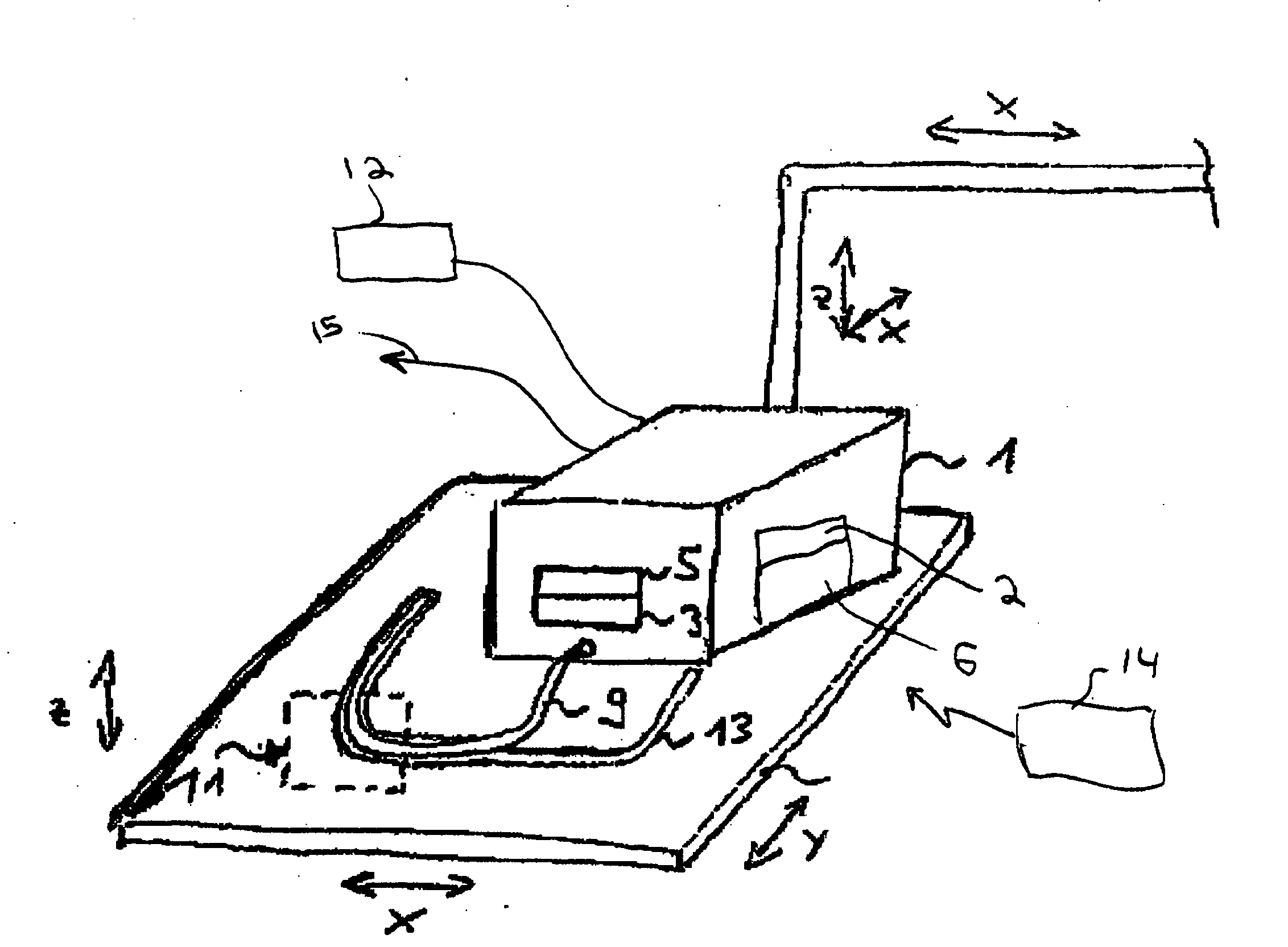
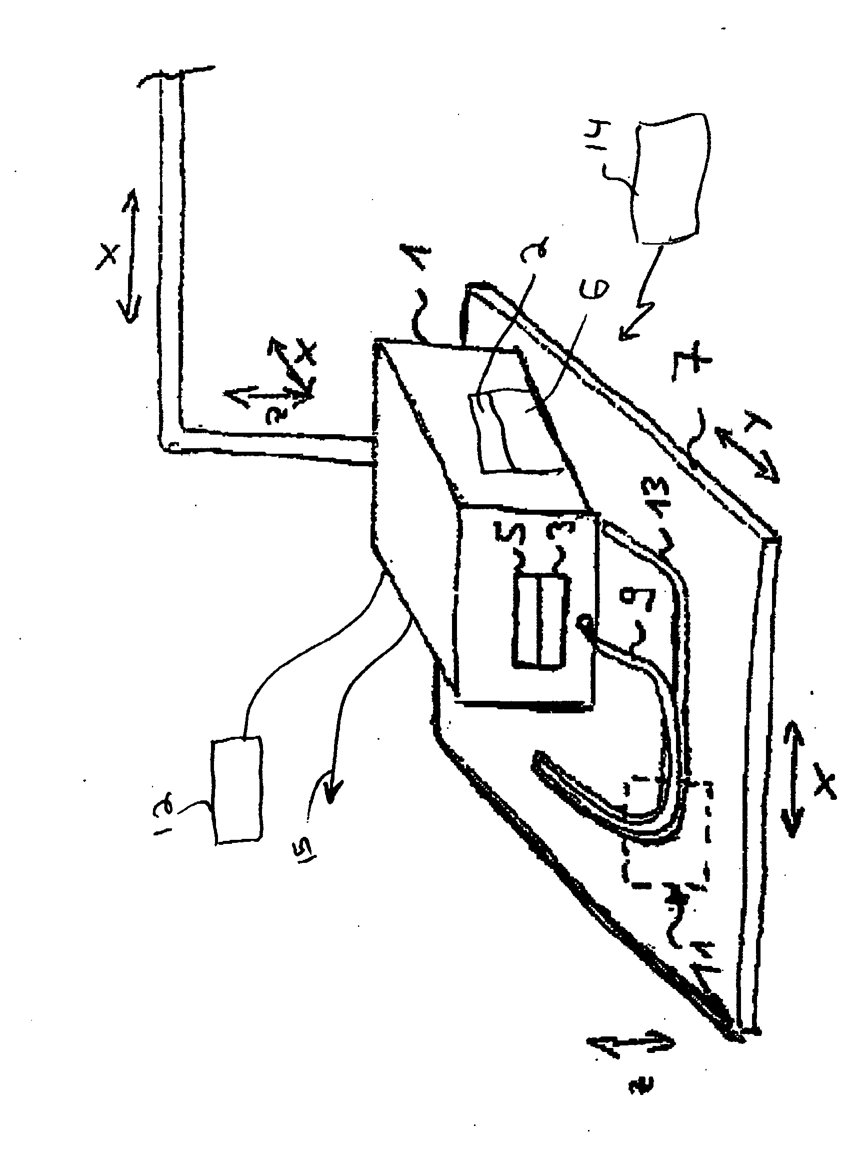
[0006] A sensor unit is provided on the facility for the application of the structure. By this means, a
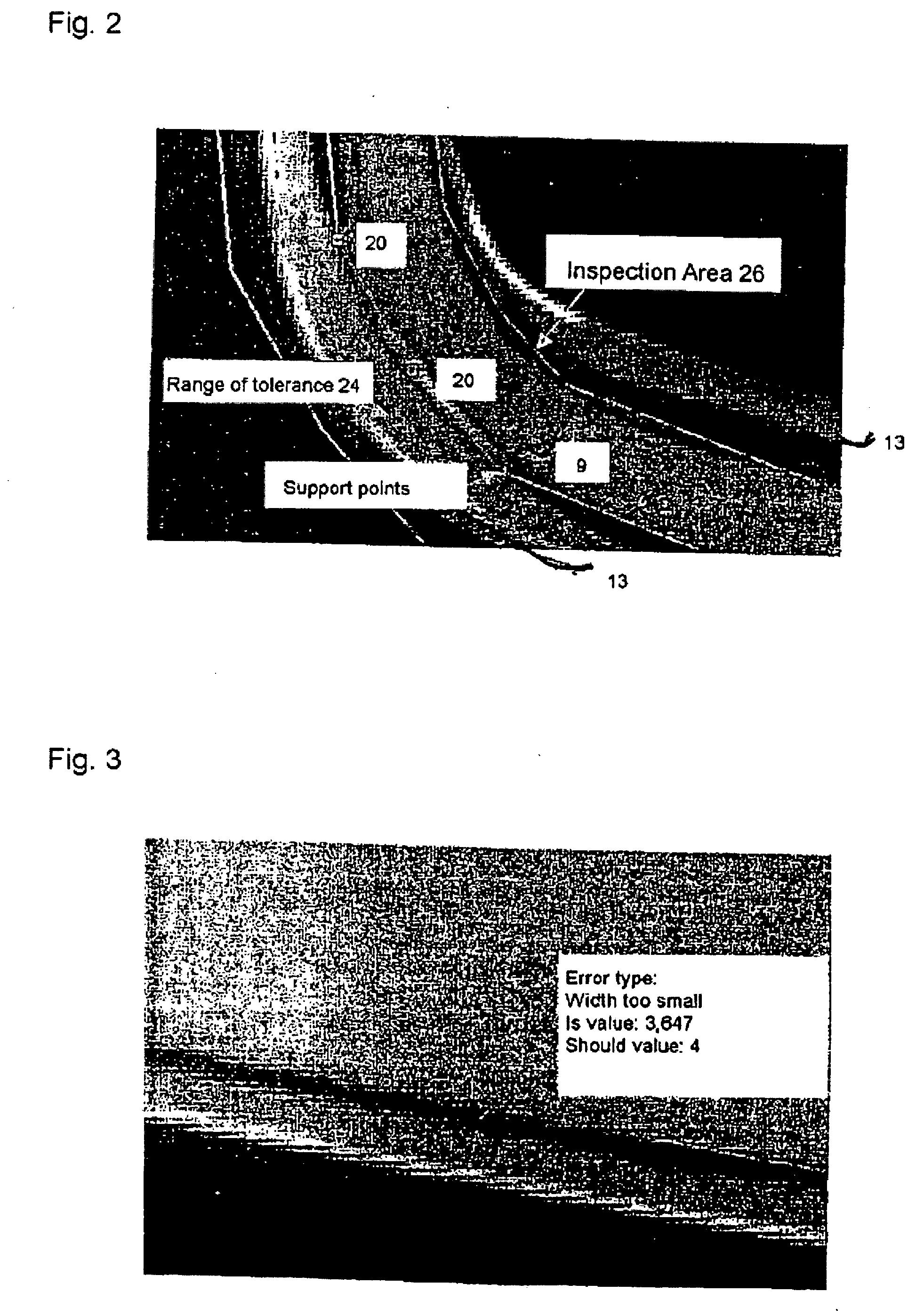
visual inspection system with a compact design is provided, whereby the illumination module can preferably also be provided on the facility for the application of the structure. This facilitates the integration of the device according to the present application into existing systems whose task it is to apply a structure to a substrate. While the structure is applied to the substrate, if an error is present, it is feasible to directly act or interrupt during the manufacturing process and / or sort out the defective substrate. This provides for improved efficiency in the manufacture of structures on a substrate. If the method involves a tested area of the structure that is placed along the structure to be tested by means of support points, the handling becomes trouble-free since the interactive process between the user and the displayed structure is implemented in a simple fashion with currently existing means. If, according to the invention, the range of tolerance is set along the
reference line defined by the support points, inaccuracies of the structure, if any, will be accounted for and, in particular, the quality inspection of the structure to be tested can be set individually by this means. This simplified operator interaction allows even complex track profiles of the structure to perform a teach-in process in a simple and efficient fashion. Moreover, the existing display visualizing the structure and the
reference line generated by the support points indicates directly to the user whether or not deviations in the track profile of the structure are present.
[0008] By positioning the sensor unit directly at the exit of the facility for the application of the structure, it becomes feasible to provide a compact and highly-integrated implementation of the device. Therefore, the sensor unit is capable of
fully automatic high-speed inspection of the structure almost directly after its application. The sensor unit comprises a video-sensor, and may use various
image detection procedures. The video-sensor may comprise one and / or several picture lines, (e.g., 15 lines), such that a high
image recording rate can be achieved. By this means the device stays small in size and the
image analysis can be performed in the sensor unit such that no
external data analysis facility is needed.
[0009] The use of a
white light illumination module as illumination module allows the use of conventional
halogen lamps also for the generation of
white light. The use of an
LED illumination module as illumination module allows for the provision sensor illumination for improved contrast between background and structure by skillfully combining different spectral ranges. The analysis as such can therefore proceed in a stabile fashion and the
resource use involved in the analytical logics is minimized also. The same applies in particular to the provision of multiple illumination modules, which can therefore provide for improved contrast. If, in addition, the analytical unit is integrated in the sensor unit, it becomes easy to add to the device the feature of setting the quality criteria in a simple fashion by means of an external
control unit. The transmission preferably is mediated by radio,
infrared data or cable.
[0010] If the method used involves that the structure is determined by means of so-called calipers (gray edge scanning), which preferably extend orthogonal to the structure on the substrate, this means can be used to define specific areas, preferably crossing areas, between the caliper line and a contrast structure in the area to be determined. If the calipers extend orthogonal to the structure on the substrate, this allows especially the width of the structure to be determined in a simple fashion. In conjunction with appropriate
visualization software, the profile of the structure and the corresponding areas of error can be displayed. The user thus recognizes immediately whether or not the profile of the structure complies with the given range of tolerance or if the structure is being applied inaccurately. Another
advantage is provided by making it feasible to base the structure determination and corresponding
error analysis for example on the given substrate data, such as recesses and elevations, since this allows more exact statements concerning the profile of the structure to be made.

