Injection molding system for injection molding a plurality of materials

a technology of injection molding and materials, applied in the direction of sweetmeats, dough shaping, food shaping, etc., can solve the problems of valve pins creating undesirable shear on molten materials, poor flow of molten molding materials, and degrading the material quality and appearance of molded parts, so as to improve the flow of molten materials and improve the injection molding process. , the effect of more control over the injection molding process

Active Publication Date: 2006-07-06
PLASTIC ENG & TECHN SERVICES
View PDF23 Cites 17 Cited by
  • Summary
  • Abstract
  • Description
  • Claims
  • Application Information

AI Technical Summary

Benefits of technology

[0014] One advantage of the present invention is that an injection molding system is provided for injection molding a plurality of materials into a mold cavity. Another advantage of the present invention is that the injection molding system is provided with an actuator assembly that can individually allow a plurality of molten materials to flow into a mold cavity. A further advantage of the present invention is that an injection molding system is provided with flow passages positioned such that heat can be more evenly transferred to the molten material, thereby providing more control over the injection molding process. Another advantage of the present invention is that the injection molding system improves the flow of the molten material because the valve member is largely isolated from the flowing molten material and because the flow passages are sized to sustain more even pressure in the molten material. Yet another advantage of the present invention is that the injection molding system provides a great deal of control over the flow of the molten materials, improving the material quality and appearance of the molded part.
[0015] Other features and advantages of the present invention will be readily appreciated, as the same becomes better understood, after reading the subsequent description taken in conjunction with the accompanying drawings.

Problems solved by technology

One disadvantage of the above-described injection molding systems is that the flow of the molten molding materials is typically poor, thereby potentially degrading the material quality and appearance of the molded part.
For instance, the valve pin creates undesirable shear on the molten material as it flows past the pin.
Furthermore, pressure can build within the flowing molten material due to improperly sized flow passageways, especially near the gate.
These factors can degrade the flow of the molten materials, giving users less control over the quality of the molded part.
These factors also often cause an undue amount of residual molding materials to remain within the passageways after completing the molding process.

Method used


Image

  • Injection molding system for injection molding a plurality of materials
  • Injection molding system for injection molding a plurality of materials
  • Injection molding system for injection molding a plurality of materials

Examples


Embodiment Construction

)

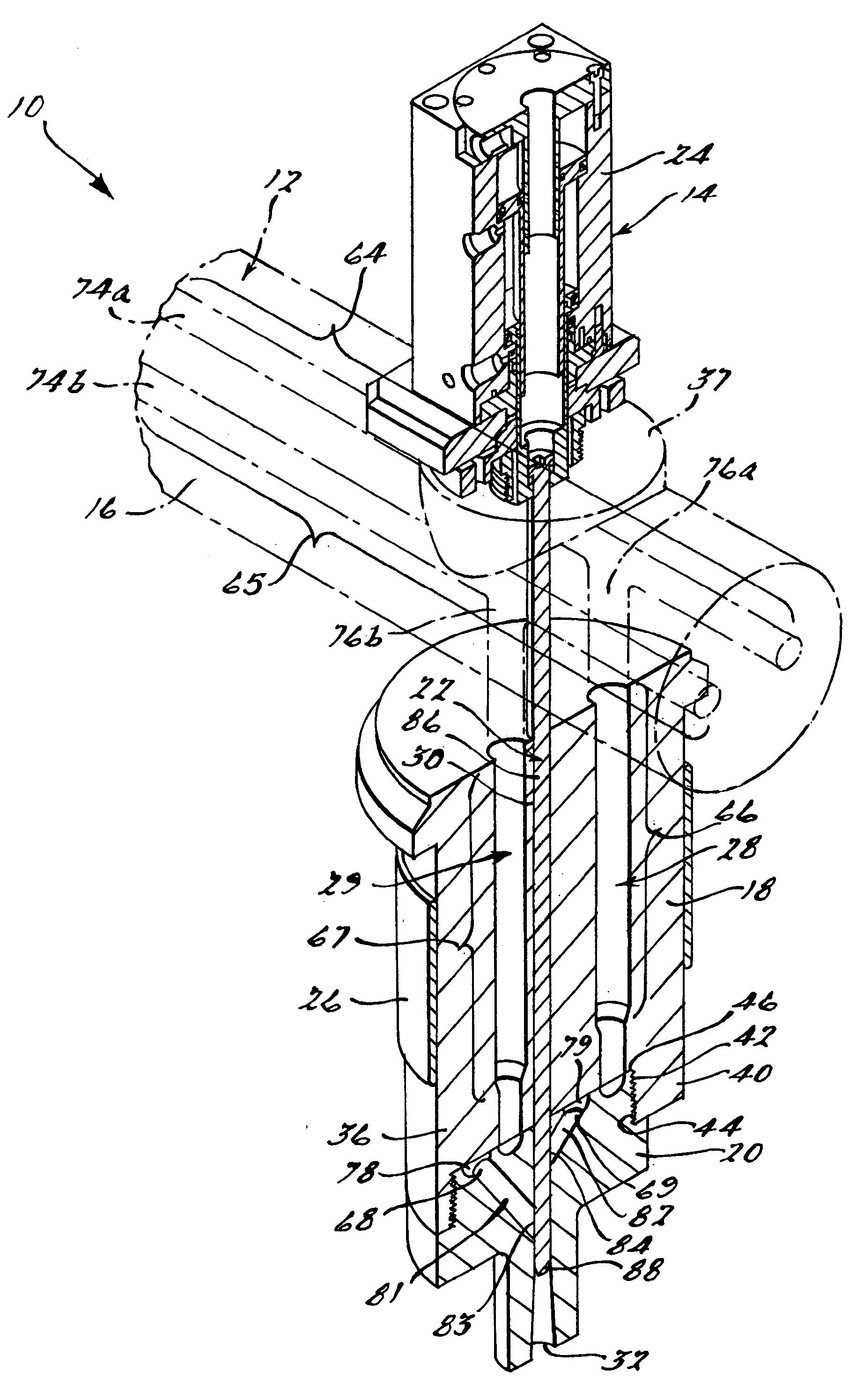
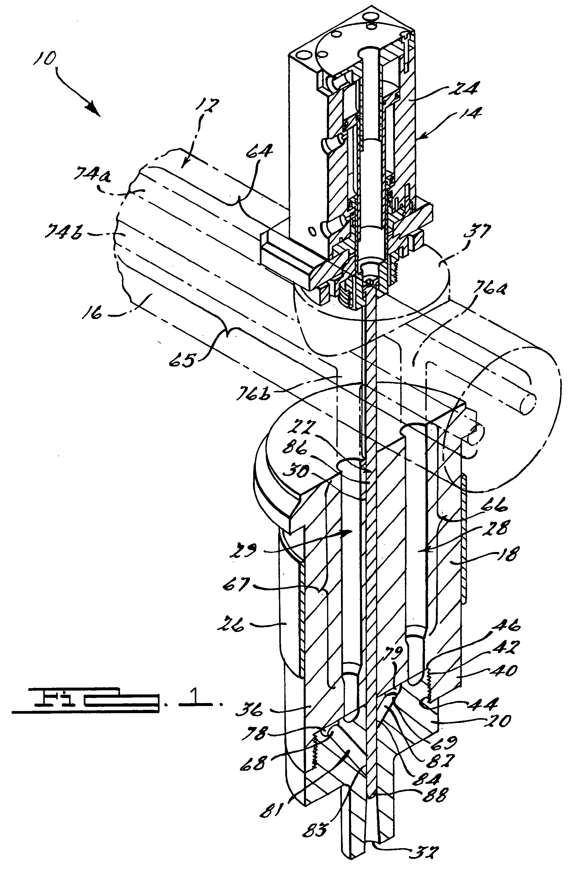
[0019] Referring to the drawings, and in particular FIG. 1, one embodiment of an injection molding system 10, according to the present invention, is shown. The injection molding system 10 includes a manifold assembly, generally indicated at 12, and a valve gate assembly, generally indicated at 14. The manifold assembly 12 generally includes a manifold 16, at least one nozzle 18 extending outwardly from the manifold 16, and a drop tip 20 operatively supported by the nozzle 18. It should be appreciated that the manifold assembly 12 can include more than one nozzle 18, each with an attached drop tip 20. The valve gate assembly 14, on the other hand, generally includes a valve member 22, and an actuator assembly 24 operatively attached to the valve member 22. The injection molding system 10 further includes at least one, preferably a plurality of heat sources 26 mounted to the manifold 16 and nozzle 18.

[0020] The injection molding system 10 includes a first flow passage, generally ind...


PUM

PropertyMeasurementUnit
distancesaaaaaaaaaa
distanceaaaaaaaaaa
inner diameteraaaaaaaaaa

Abstract

An injection molding system for injection molding a plurality of molten materials into a mold cavity includes a nozzle, a drop tip supported by the nozzle, and a central bore extending through the nozzle and drop tip. The injection molding system also includes a first and second flow passage each extending through the nozzle, so as to define a first and second nozzle flow passage, and drop tip, so as to define a first and second drop tip flow passage. The first and second drop tip flow passages each include a plurality of branching portions each defining a junction at which the respective flow passage communicates fluidly with the central bore.

Description

CROSS-REFERENCE TO RELATED APPLICATION(S) [0001] The present application claims the priority date of copending U.S. Provisional Patent Application Ser. No. 60 / 641,252, filed Jan. 4, 2005.BACKGROUND OF THE INVENTION [0002] 1. Field of the Invention [0003] The present invention relates generally to injection molding systems and, more particularly, to an injection molding system for injection molding a plurality of materials. [0004] 2. Description of the Related Art [0005] Injection molding is a widely known manufacturing process used to produce a variety of parts. Injection molding involves introducing a molten material, such as a molten plastic or resin, into a cavity within a mold. The molten material hardens or cures in the mold in the shape of inner surfaces of the cavity. Then, the cured material is removed from the cavity. [0006] A typical injection molding system includes a manifold assembly used for conveying molten material from a source such as a nozzle of an injection moldi...

Claims


Application Information

Patent Timeline
Patent Type & Authority Applications(United States)
IPC IPC(8): B29C45/20
CPCB29C45/1603B29C45/22B29C45/23B29C45/17B29C45/16
Inventor TOOMAN, PATRICK A.
Owner PLASTIC ENG & TECHN SERVICES
Why Eureka
Try Eureka