
Optical data recording medium and manufacturing method for the same, and a method for clamping the optical data recording medium

a technology of optical data and manufacturing method, which is applied in the direction of flat record carrier container, instruments, other domestic articles, etc., can solve the problems of easy scratching of the protective layer, loss of servo control, and increase the film thickness, so as to achieve good signal quality, easy to form the protrusion, and easy to scratch the protective layer

Inactive Publication Date: 2006-07-06
PANASONIC CORP
View PDF19 Cites 9 Cited by
  • Summary
  • Abstract
  • Description
  • Claims
  • Application Information

AI Technical Summary

Benefits of technology

"The present invention provides an optical data recording medium with a transparent protective layer that can prevent scratches and reduce the load on the motor during rotation. The medium also has higher data transfer rates and can apply higher clamping force. The invention solves three problems faced by high density optical discs: surface scratches caused by a weight imbalance in the protective layer, increased load on the motor due to a weight imbalance, and interference between the optical head and the center hole of the disc. The solution is to provide a protrusion on the surface of the transparent protective layer in the clamping area and the signal recording layer. The protrusion prevents interference with the optical head and keeps the transparent protective layer raised above the flat surface, reducing scratches and improving cost."

Problems solved by technology

A problem with high density optical discs is that the surface of the transparent protective layer is easily scratched, and scratches can easily cause a loss of servo control.
Increasing the mechanical strength of the transparent protective layer itself increases the film thickness, and is not suited for high density recording.
It is therefore difficult to protect the surface from scratching while keeping the transparent protective layer thin.
In addition, high speed rotation of these high density optical discs also requires higher disc clamping force than CD and DVD discs.

Method used


Image

  • Optical data recording medium and manufacturing method for the same, and a method for clamping the optical data recording medium
  • Optical data recording medium and manufacturing method for the same, and a method for clamping the optical data recording medium
  • Optical data recording medium and manufacturing method for the same, and a method for clamping the optical data recording medium

Examples


embodiment 1

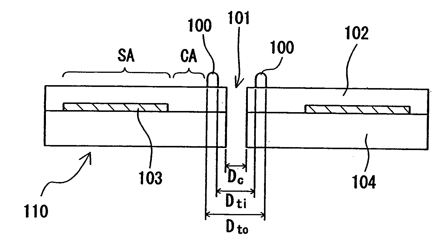
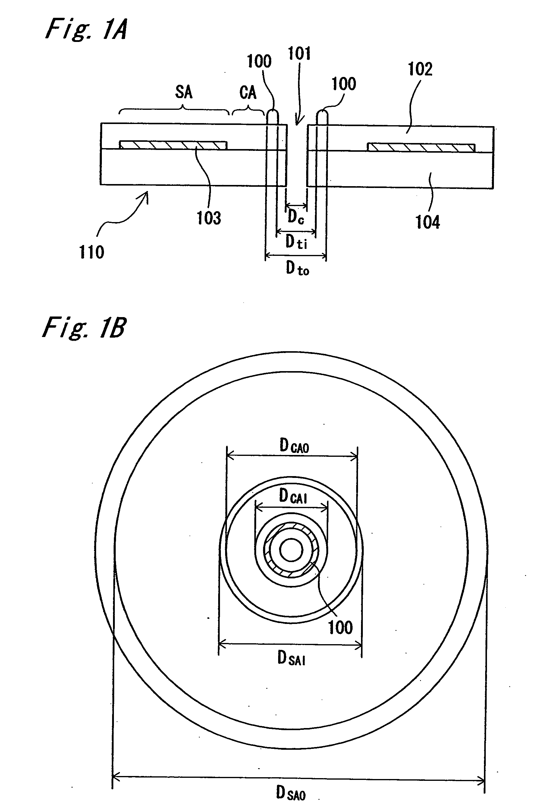
[0078]FIG. 1A is a side section view of a preferred embodiment of an optical data recording medium according to the present invention. The optical data recording medium 110 (also referred to below as simply “disc”) shown in FIG. 1A has a protrusion 100 disposed on the surface thereof between the inside circumference side of the clamping area CA and the outside edge of the spindle hole 101. FIG. 1A is a section view of this optical data recording medium 110, and FIG. 1B is a top plan view of the optical data recording medium 110.

[0079] The outside diameter of this optical data recording medium 110 is 120 mm. The clamping area CA is the area where the optical data recording medium 110 is clamped and held when reading and / or writing data to the signal recording layer 103. The inside diameter DCAI of the clamping area CA is 22 mm and the outside diameter DCAO is 33 mm.

[0080] A transparent protective layer 102 protects the signal recording layer 103. A light beam with a 405 nm waveleng...

embodiment 2

[0127]FIGS. 8A and 8B show an optical data recording medium 810 having a protrusion 800 disposed in the area between the clamping area CA and signal area SA. FIG. 8A is a section view and FIG. 8B is a plan view from the transparent protective layer 802 side of the disc. The inside diameter and outside diameter of the clamping area CA and signal area SA are the same as in the first embodiment. The thickness of the transparent protective layer 802 is also the same as in the first embodiment. In this example the inside diameter Dti of protrusion 800 is 33 mm (=DCAO), and the outside diameter Dto is 35 mm. The height Ttcv of the protrusion 800 is 0.25 mm. The protrusion 800 is formed on the surface of signal substrate 804.

[0128]FIG. 9 is a partial section view when reading and / or writing the optical disc.

[0129] When recording or playing a high density optical disc with a 0.1 mm thick transparent protective layer on the laser incidence side (the read / write side) of the disc using a 0.7...

embodiment 3

[0139] An optical data recording medium in which the protrusion is located in the clamping area CA is shown in FIGS. 11A-11C as a third embodiment of the present invention. FIG. 11A is a section view of the disc.

[0140] The inside diameter Dti and outside diameter Dto of the protrusion 1100 are defined by the following relation.

DCAI<=Dti<Dto<=DCAO

[0141] This configuration also prevents scratching when the optical data recording medium 1110 is placed on a flat surface with the transparent protective layer 1102 facing the flat surface because the protrusion assures a sufficient gap between the transparent protective layer 1102 and said flat surface.

[0142] Collision of the optical head with the protrusion is also prevented because the optical head does not enter the clamping area CA.

[0143] Note that the thickness of the transparent protective layer, inside diameter DCAI, and outside diameter DCAO are the same in this embodiment as in the first embodiment.

[0144] The width ...


PUM

PropertyMeasurementUnit
thickaaaaaaaaaa
heightaaaaaaaaaa
protrusion heightaaaaaaaaaa

Abstract

A disc-shaped optical data recording medium has a signal recording layer for reading and / or writing data using light, and a 10 μm to 200 μm thick transparent protective layer disposed over the signal recording layer. The optical data recording medium includes a protrusion projecting from a surface of the transparent protective layer on a light-incidence surface side to which light is emitted to the signal recording layer. The protrusion is disposed in an area between a center hole and a clamping area where the optical data recording medium is held when reading and / or writing data in the signal recording layer.

Description

[0001] This application is a divisional application of application Ser. No. 10 / 655,135, filed Sep. 5, 2003.BACKGROUND OF THE INVENTION [0002] 1. Field of the Invention [0003] The present invention relates to a disc-shaped optical data recording medium having a signal recording layer for recording and / or playing information by emitting a light beam thereto, and a transparent protective layer 10 μm to 200 μm thick disposed over the signal recording layer. The invention also relates to a method for manufacturing this optical data recording medium, and to a method for clamping the optical data recording medium. [0004] 2. Description of Related Art [0005] Optical discs are known and widely used as a high capacity data storage medium for high density recording and playback of information using a laser beam. These optical discs are broadly categorized as read-only, incrementally writable (multisession), and rewritable. Typical of read-only discs are Compact Discs (CDs) storing audio conten...

Claims


Application Information

Patent Timeline
Patent Type & Authority Applications(United States)
IPC IPC(8): G11B7/24G11B23/03B29C45/26B29D17/00G11B7/24047G11B7/26G11B17/028
CPCB29C45/263B29C2045/2661B29C2045/2667B29D17/005B29L2017/005G11B7/1201G11B7/24003G11B7/24097G11B7/263G11B17/0284G11B23/0035G11B7/121G11B7/24027G11B7/26
Inventor HAYASHI, KAZUHIROOHNO, EIJIMOHRI, MASANARI
Owner PANASONIC CORP
Learn More